CH341 mod for 3,3V 2021.07.12 at 11:58
Thought I will write this post in English. Not because its something global, but to practice the language. For a long time used the Chinese programmer CH341, basically for 5V IC’s, but now I needed to program BIOS on the video card (should be separate post about the repair of it). The EPROM with BIOS should be powered by 1,8V and I was surprised, that originally it is powered by 3,3V, by the power supply on the video card. Not much of a help, because I did not have a 1,8V or 3,3V programmer. But I remember, when I received couple of CH341’s I saw a 3,3V converter on board. It uses AMS1117 chip to make 3,3V, but strange – there is no way to switch to 3,3V power supply for the programmed IC. I mean, the CH341 is always powered by 5V from USB, and it cant be switched to have 3,3V on the programming pins (CS, CLK, MISO, MOSI, etc). Its, probably, a mistake, made by the creator of that PCB. A mistake, which can be easily corrected.

Lets analyze a bit how to properly do the 3,3V mod. First, the AMS1777. It looks like a clone of LM1117 by Texas Instruments :D.
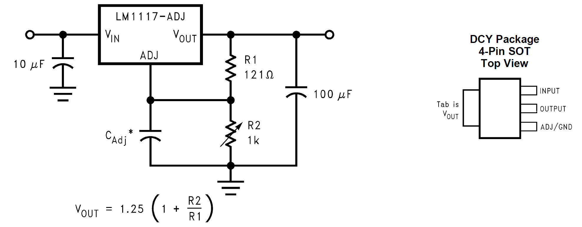
The middle pin and tab of the package are outputs, giving 3,3V, we will take them from here.
While writing this found the CH341 programmer schematics:

The CH341 chip has only one positive power supply pin, so we will have to disconnect it from 5V and connect it to 3,3V. This should make it output 3,3V on all pins. According to CH341 datasheet, it supports both 5V and 3,3V, so we’re OK here. The datasheet is written in Chinglish, so I had to think what the hell do they mean by this:
CH341 support 5V and 3.3V source voltage. When working on 5V source voltage, the VCC input 5V
power from outside, and V3 connects to 4700pF or 0.01uF decoupling capacitance. If the work power is
3.3V, connect V3 to VCC, input 3.3V source voltage. The voltage of other circuit which is connected to
CH341 is no pass than 3.3V.
I decided, that this means if chip is powered by 3,3V, I should connect the V3 (pin 9) to VCC. Leaving the last sentence for you to crack :D.
The work took just a couple of minutes – lifted the pin 28 from PCB, soldered one strand of copper wire, routed that wire to pin 9, soldered to pin 9 and went to the finish on the 1117 tab. Looks like this:
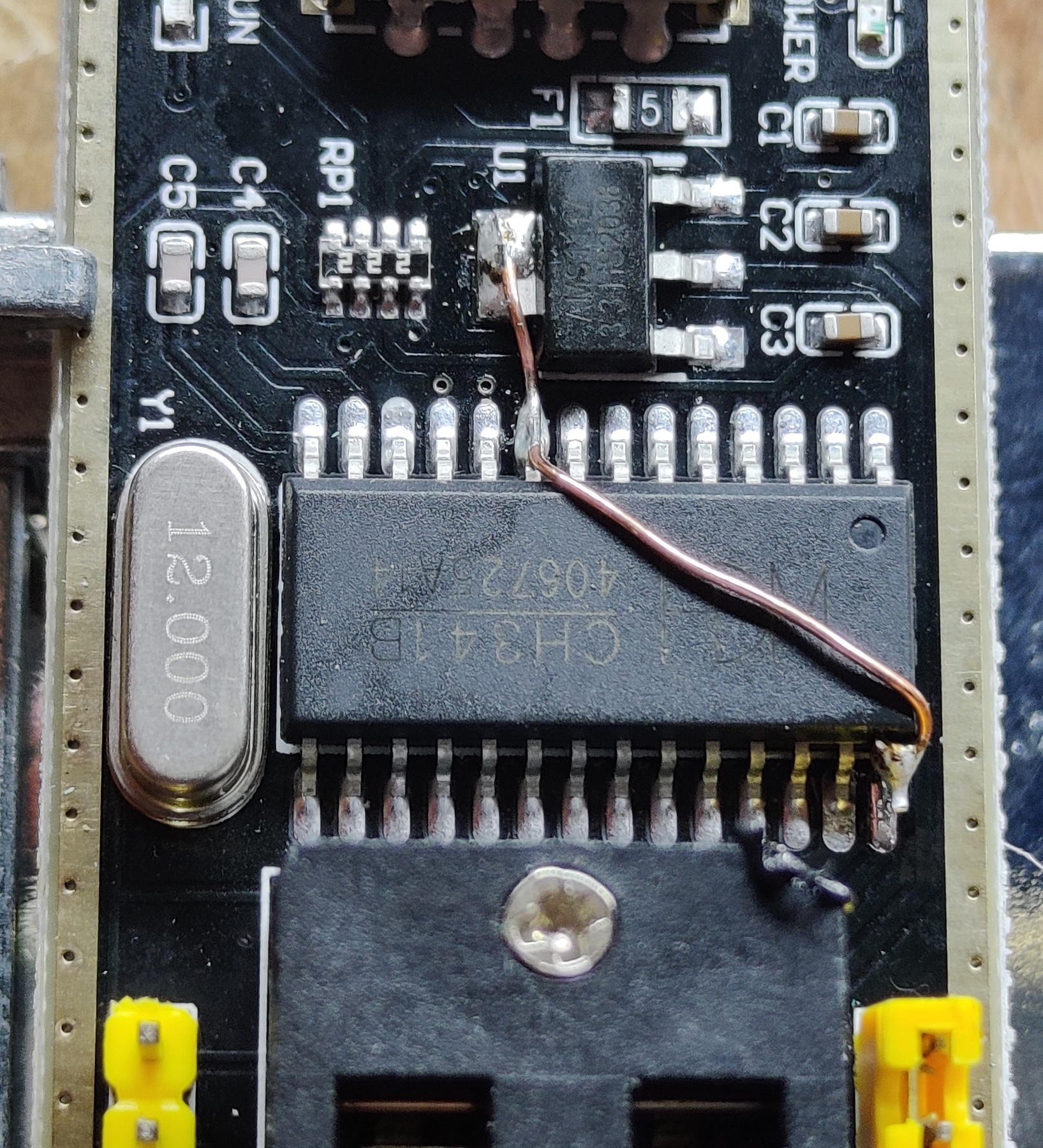
Surprisingly – it reads and writes the BIOS on the video card, thus leaving it in my programmers box as a cheap but still useful tool.

Leave a Reply