12V į 5V USB adapteriukas iš Kinijos 2012.05.29 at 15:32
Jei konkrečiai tai kalba eina apie šitą:
http://dx.com/p/universal-2000ma-usb-car-charger-adapter-for-digital-devices-black-12-24v-72961
Paprastas, mažiukas, patogus. O ir parametrai įspūdingi:
– Color: Black
– Ultra-mini size USB car charger
– Plugs into your car’s cigarette lighter jack to become a powered USB port
– Input: 12~24V
– USB power port
– Output: 5V / 2000mA
– Built-in circuit protection, over heat, over loaded protection
– Compatible with digital devices with 5V / 2000mA input
Įdomu, ar viskas čia yra taip kaip parašyta :), patikrinsim. OK, kad juodas ir kad mažas ir taip aišku, kad jungiasi į mašinos 12V lizdą niekas nesiginčija. Nuo 12V ir 24V dirba. Ilgai nelaikiau, kokia 20 sekundžių, bet nesusvilo iškarto tai laikys ir ilgiau. Jei nebus jam per karšta. Kintant nuo 12V iki 24V išėjimas apie 5V, apkrovą užkabinau kuri valgo 1,0A. Nieko blatno – nichromo vielikė. Kad USB power port tai turbut ir taip aišku. Ir USB ir power. Tep, daba apie išėjimą. Pradžiai 12V įėjime be apkrovos:
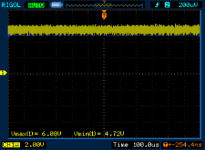
 Ir ką mes čia matom… Įtampa tai nestabili, kinta nuo 5,28V iki 5,6V. Nieko gero… O vat čia vaizdelis su minėta apkrova @ 1A:
Dar blogiau… Apkrova valgo tik pusę deklaruojamos srovės o įėjime turim belekokį bardaką ir tik 2,72V-3,04V.
Tas pats bandymas su 24V įėjimu:
Vaizdas dar blogesnis – ant tuščio 4,72V-6,08V, su apkrova 2,88V-3,28V. Taigi, iš tų deklaruojamų dviejų Amperiukų net pusę nedalyvauja susirinkime…
Ok, dabar biškį teorijos.
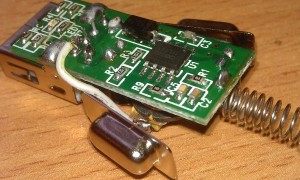
Schemos pagrindas – CX8505 aštuonkojis. Tipinė jungimo schema:
 Išėjimo įtampa nustatoma dalikliu, paskaičiuojama Vout = 0,925 · (1 + R1/R2). O toliau čia daug maž paprastas Buck tipo konverteris…
Kojų „raspinovkė”:
1 – BS – MOSFETo papildomas/pagalbinis maitinimo kondensatorius. Kondensatorius jungiamas tarp BS ir SW kontaktų laiko papildomą krūvį aukštos pusės MOSFETui ir pašeria jį kai MOSFETas įjungiamas. Įprastai naudojami nuo 100nF iki 1uF kondensatoriai.
2 – IN – įėjimas, nuo 4,75V iki 18V.
3 – SW – impulseko išėjimas į LC kontūrą.
4 – GND – GND 😀
5 – FB – grįžtamasis ryšys (feedback). Daliklis turi būti paskaičiuotas taip, kad koja gautų 0,925V.
6 – COMP – kompensacinė dalis. Nuosekliai sujungta RC > GND grandinė naudojama kompensuoti valdymą esant closed-loop schemai.
7 – EN – įjungimas. Prijungtas prie aukšto lygio įjungia konverterį. Pajungus per 100K pull-up’ą – automatinis įjungimas.
8 – SS – lėto paleidimo kontaktas. Pajungus kondensatorių tarp SS ir GND nustatomas soft starto laikas. 0,1uF kondensatorius duoda apie 15 mS užlaikymą. Jei funkcija nenaudojama kontaktą galima palikti neprijungtą.
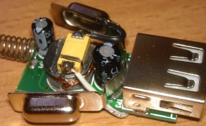
Deklaruojami 3 A išėjime tikėtini, bet reikia nepamiršti storesnių laidų. Kadangi čia visgi yra impulsinis maitinimo šaltinis išėjimas turėtų būti stabilesnis. Kaip turėti gražesnį rezultatą išėjime ? Nu… Bandom. Pirmas dalykas – išėjimo kondensatoriaus talpa yra mažoka (100 uF x 16V), priklijuojam papildomai D dydžio tantaliuka (470uF x 6V).
Štai ir viskas, papildomas kondensatorius priklijuotas su termoklijais, uždarytas dangtelis ir bandymas be apkrovos…

… ir jau su apkrova, srovė 2,4A (dešinėje).
Ar matosi skirtumas 🙂 ? Va, dabar jau galima sakyti, kad impulsekas veikia. Beje, pamiršau paminėti tai, kas ir taip akivaizdu – išėjimas žymiai stabilesnis, reiškia ir maitinamai apratūrai bus ramiau. Įtampa aišku pakrenta prie tokios apkrovos, tai gali būti ir dėl mano naudoto laido – plonas ir pusmetrinis, o matavau jo gale… Ną, sveika būtų ir droseliuką papimpinti 🙂


Noreciau su jumis pakalbeti del vieno projekto. Gal galit brukstelti man email – nerandu jusu email.
Brukstelejau 🙂
Is it still working?
Yes it is. Though to have final upgrade one should replace the coil. IT would add more stability to current, supplied from adapter on hi loads.
Thank you for your comment at DX. Can you explain in short words what you have done ? For me (I used google translater) it seems there is a thermal problem and you solved it, right (see your last picture) ? Thanks for your support.
Hi Hugo, its not the thermal problem (it might be, but if I remember correctly CX8505 has thermal shutdown, so it would just turn off until heat is gone). What I tried to do is to improve voltage and current stability. This is shown by oscilloscope screenshots. First of them – input 12VDC, output from 5,28V to 5,6V without load (naturally – its not good, especially when rated 5V at 2A). Second screenshot is 12V input, but only 2,72V-3,04V output at 1A current. This is only half of declared voltage so, already the device cant hold the load. Next two screenshots are for 24V – first without load (4,72V-6,08V, by the way – 6,08V might be bad for some devices), with load, which creates 1A current we have only 2,88V-3,28V – again, only half of rated voltage at half load (according to description it should be 5V at 2A). Then a little theory, in fact CX8505 can supply current up to 3A, so it must be other components, that aren’t letting the device to work. This is impulse type voltage converter and they have several weak spots – first the capacitor was too small (100 uF x 16V), so soldered and hotglued additional D size tantalum cap (470uF x 6V). And the last two screenshots I put side by side, for easy comparison, left is without load, right is with load at 2,4A! So, only the bigger capacitor increased voltage stability (oscilloscope setting not changed, so you can even see that on screen, without any numbers) at much much bigger current (2,4A – more than twice). Simple as that. This is easy, but there is some more things to upgrade, to achieve even more stability at hi loads, but my intention was to have a cheap upgrade of a cheap power supply, so I just done that 🙂 Hope its clear enough, if not – just ask.
You write „additional D size tantalum cap”, so the original cap with 100uF is still there and you added the 470uF. Ok, now I understand and now I see the wire of the 470uF cap in your last picture (that was hard to detect 🙂
Would it be ok to use other caps than a Tantal ? For example a normal cap like the black one that are built in ? What about the voltage of the additional cap, must it be 6V ?
Thank you (more then 20 years ago that I learned Electrical Engineering and since then I did not work with it anymore 🙁
Good to be back to electronics 🙂 ? So, you are right, the yellow thing on the top of coil ferrite is tantalum capacitor and yes, it it in parallel with original capacitor, so, the capacitance is the sum of both capacitors. You can use any capacitor with similar or bigger capacity, the voltage cannot be lower than working – in my measurements (we saw it) it was about 6V, though with 12V input there were less, so I took 6V cap. Why ? Simple – bigger voltage caps are bigger, and there is no space for it. Also, preferably, cap should be low ESR. But if you manage to put the bigger voltage cap – its OK. There is several things you should know when choosing this capacitor – space (bigger voltage and/of capacitance might not fit inside), ESR – preferably lower (tantalum caps tend to have lower ESR than those black electrolytic caps), both – black and tantalum caps are polarized, so don’t mix plus with minus. There is some more things that could be taken into account (like dV/dt, max current, max frequency), but for this particular schematics they are not crucial.
very cool, thanks a lot