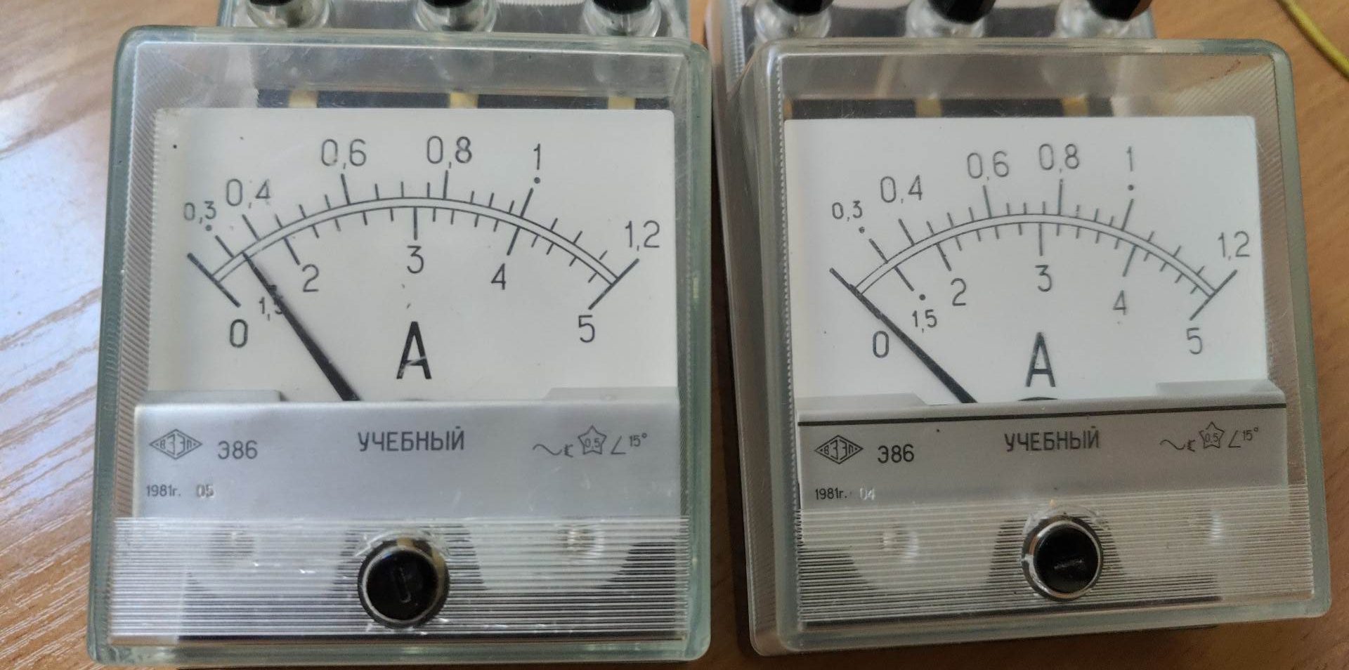
Toks labai paprastas ir lengvas remontukas tiems atvejams, kai jau gamykliškai ampermetro neįmanoma nustatyti ties nuline padala. Pavyzdyje kairys ampermetras dabar arčiausiai nulinės padėties pagal reguliavimo rankenėlę, bet vis tiek rodo 1,5A (5A skalėje). Dešinys – rodo nulį teisingai.
Ardome, tam reikia atsukti 2 varžtelius po kontaktinėmis jungtimis, nuimti nedideli dangtelį. Po dangteliu kontaktinių jungčių varžtai, juos atsukus korpusas atsidaro. Tuomet reiktų atsukti dar du mažiukus vartelius, kad nuimti priekinę skardelę. Dabar jau matosi rodyklės ašis, spyruoklė, ritė ir magnetukas. Įsitikiname, kad rodyklė tiesi. Pastačius reguliavimo kilpą vertikaliai, atlenkiame kairėje esantį stačiakampį metalinį daikčiuką (pažymėtas raudonu kvardatu) tiek, kad pakiltų iš savo griovelio ir sukame jį taip, kad rodyklė atsistotų į nulinę padėtį.
Viskas. Surenkame atgal, reguliavimo rankenėlė vis dar reguliuoja rodyklės padėtį, viskas kaip ir veikia.
Kodėl taip atsitiko ? Visai nebūtinai ampermetras gavo per daug srovės, pamatavo įtampą vietoje srovės ir panašiai, tiesiog – rusiškas daiktas, darytas kirviu ir 13 raktu, o dar ir mokykloms, ne karinei pramonei, tai toks ir tikslumas, ir broko kiekis. Va būtų truputį kitu kampu tą griovelį prafrezavę ir viskas gerai būtų.
This one is for my friend Nico and other readers who knows English. Some readers remember, that we already tested the work of DS18B20 with Atmega328P on Arduino board, that was easy, because of ready libraries. But lets put away toys and use STM32F466RE on Nucleo-F446RE development board. We already have LCD display outputting some information, so lets use it to display temperature, but we will not use DMA this time. First, lets prepare the DS18B20 sensor for connection with microprocessor. The only required thing in 3 wire configuration is 4,7 kΩ pull-up resistor:
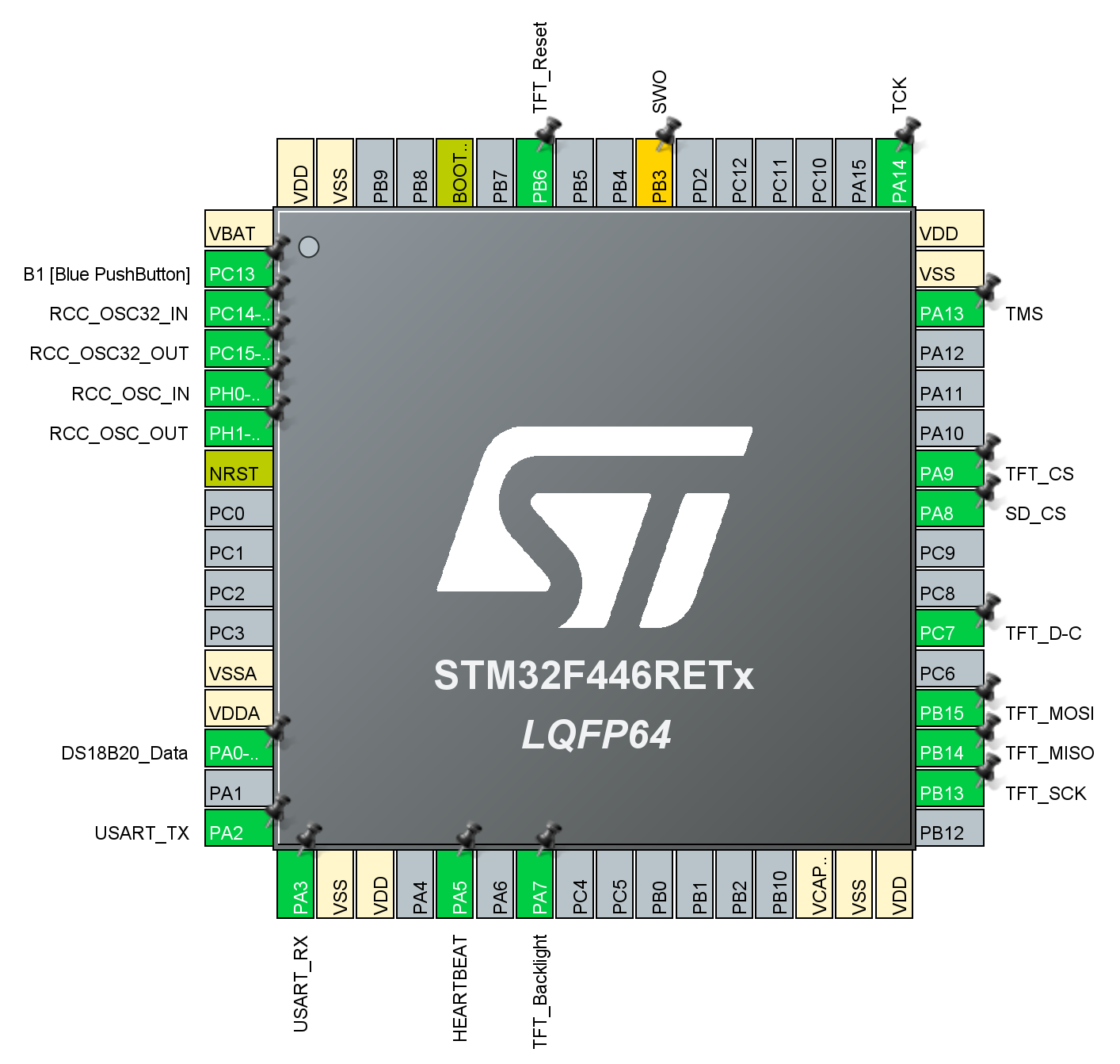
Thus, between positive power (+3,3V or +5V) and DQ (data) wires connected 4,7 kΩ resistor. If the microprocessor or microcontroller has internal pull-up resistors, they might be enabled in program, so we wouldn’t need additional external resistor. Next – let’s connect the sensor and configure STM32 to use LCD and assign pin for DS18B20. Connection is easy, used +3,3V, GND and PA0 pins. Why PA0 ? Because its closest to power pins:
Could be any other pin, which can be configured as GPIO_Output. Later we will also try enabling the internal pull-up and dropping the external resistor. After configuring the microprocessor pins, view should be similar to:
Pins:
DS18B20_Data – GPIO_Output, PA0 pin, where we connected the Data (DQ) pin of the DS18B20;
HEARTBEAT – GPIO_Output, PA5 pin, this pin has LED connected, used for troubleshooting and will not be used in the final program;
TFT_SCK – SPI2_SCK, PB13 pin, used to clock the LCD;
TFT_MISO – SPI2_MISO, PB14 pin, used for MISO data (Master Input, Slave Output);
TFT_MOSI – SPI2_MOSI, PB15 pin, used for MOSI data (Master Output, Slave Input);
TFT_D-C – GPIO_Output, PC7 pin, D/C signal for LCD (Data/Control);
SD_CS – GPIO_Output, SD card Chip Select signal, not used in our program;
TFT_CD – GPIO_Output, TFT Chip Select signal;
TFT_Reset – GPIO_Output, TFT Reset signal.
Ok, that is all configuration. Next – programming , step by step. First lets initialize the HEARBEAT, so the on board LED would blink, showing, that the microprocessor is alive. To the „main(void)”, which runs only once, after the microprocessor is started:
  /* USER CODE BEGIN 2 */
  static unsigned short pin_state = 0; // Init variable
  /* USER CODE END 2 */
And:
  while (1)
  {
    /* USER CODE END WHILE */
	  HAL_GPIO_WritePin(GPIOA, HEARTBEAT_Pin, pin_state);  // Yellow LED
	  pin_state = !pin_state;
	  HAL_Delay(500);
    /* USER CODE BEGIN 3 */
  }
So, initialized the variable pin_state and in the cycle „while 1”, which is running always again and again, with each iteration doing what is inside, we change the pin_state to opposite. First line HAL_GPIO_WritePin write the pin_state to pin, thus at first iteration it writes „0” = 0V (from init variable line), then second line makes the pin_state opposite, thus „1” = 3,3V, then waist 0,5 second and then everything starts from the beginning, only that pin_state is already changed to „1” so the first line makes microprocessor pin output 3,3V and LED is ON. Easy, lets go further. We need to make the LCD work, so let’s initialize it. We can use some already made libraries, but heh, I never choose the easy way, if there is a chance to train the brains to work more. As we already know the LCD controller datasheet information, easy to define all he commands that may be used with this particular LCD:
/* Private define ------------------------------------------------------------*/
/* USER CODE BEGIN PD */
// All commands
#define NOP     	0x00 // DC = 0
#define SWRESET 	0x01 // DC = 0
#define RDDID   	0x04 // DC = 0 + 1
#define RDDST   	0x09 // DC = 0 + 1
#define RDDPM   	0x0A // DC = 0 + 1
#define RDDMADCTL   0x0B // DC = 0 + 1
#define RDDCOLMOD   0x0C // DC = 0 + 1
#define RDDIM   	0x0D // DC = 0 + 1
#define RDDSM  		0x0E // DC = 0 + 1
#define SLPIN   	0x10 // DC = 0
#define SLPOUT  	0x11 // DC = 0
#define PTLON   	0x12 // DC = 0
#define NORON   	0x13 // DC = 0
#define INVOFF   	0x20 // DC = 0
#define INVON   	0x21 // DC = 0
#define GAMSET 		0x26 // DC = 0 + 1
#define DISPOFF 	0x28 // DC = 0
#define DISPON  	0x29 // DC = 0
#define CASET   	0x2A // DC = 0 + 1
#define RASET   	0x2B // DC = 0 + 1
#define RAMWR   	0x2C // DC = 0 + 1
#define RAMRD   	0x2E // DC = 0 + 1
#define PTLAR   	0x30 // DC = 0 + 1
#define TEOFF  		0x34 // DC = 0
#define TEON  		0x35 // DC = 0 + 1
#define MADCTL  	0x36 // DC = 0 + 1
#define IDMOFF  	0x38 // DC = 0
#define IDMON  		0x39 // DC = 0
#define COLMOD  	0x3A // DC = 0 + 1
#define FRMCTR1  	0xB1 // DC = 0 + 1
#define FRMCTR2  	0xB2 // DC = 0 + 1
#define FRMCTR3  	0xB3 // DC = 0 + 1
#define INVCTR  	0xB4 // DC = 0 + 1
#define DISSET5  	0xB6 // DC = 0 + 1
#define PWCTR1  	0xC0 // DC = 0 + 1
#define PWCTR2  	0xC1 // DC = 0 + 1
#define PWCTR3  	0xC2 // DC = 0 + 1
#define PWCTR4  	0xC3 // DC = 0 + 1
#define PWCTR5  	0xC4 // DC = 0 + 1
#define VMCTR1  	0xC5 // DC = 0 + 1
#define VMOFCTR  	0xC7 // DC = 0 + 1
#define WRID2	  	0xD1 // DC = 0 + 1
#define WRID3   	0xD2 // DC = 0 + 1
#define PWCTR6   	0xFC // DC = 0 + 1
#define NVCTR1   	0xD9 // DC = 0 + 1
#define NVCTR2   	0xDE // DC = 0 + 1
#define NVCTR3   	0xDF // DC = 0 + 1
#define RDID1   	0xDA // DC = 0 + 1
#define RDID2   	0xDB // DC = 0 + 1
#define RDID3   	0xDC // DC = 0 + 1
#define GAMCTRP1   	0xE0 // DC = 0 + 1
#define GAMCTRN1   	0xE1 // DC = 0 + 1
#define EXTCTRL   	0xF0 // DC = 0 + 1
#define VCOM4L   	0xFF // DC = 0 + 1
/* USER CODE END PD */
DC = 0 + 1 means sending Command and Data, if no + 1 – then sending only command. Just my way to memorize the format of information that must be sent to LCD. When we have all the commands, lets try to initialize the LCD. We will need:
Its a bit long, but also quite clear from comments, so I’ll skip the explanation. Ok, now we have the initialization function, lets add it to be run once, after the system starts (to the main(void)):
	/* USER CODE BEGIN 2 */
	static unsigned short pin_state = 0; // Init variable
	TFT_start_init();
	/* USER CODE END 2 */
Now the microprocessor will start, init all it needs in the background, then make a variable and then TFT_start_init(). At this point decided to use ST7735 LCD controller library, just to speed up the development, but, probably, later will write a complete program without a library. So, the TFT_start_init function is doing all the things, which must be done according to ST7735 datasheet, to initialize it, and then in the end we use the library:
	ST7735_FillScreen(0x001F);  					// Set brown background
	ST7735_WriteString(0, 0, "Temperature:", Font_7x10, ST7735_YELLOW, ST7735_BLUE);
First line – filling screen with blue color, second line – writing „Temperature:” starting from coordinate 0 and 0 (x and y), with preset font and yellow characters on blue background. Good idea – later we will talk about how to create your own fonts . So now we have some of the static things, now we need to show temperature on display and it looks like this:
We will add some more static text later. Now lets try to make DS18B20 work. The datasheet says: all communication with the DS18B20 begins with an initialization, so lets do that. Datasheet explains, how to do that: During the initialization sequence the bus master transmits (TX) the reset pulse by pulling the 1-Wire bus low for a minimum of 480μs. The bus master then releases the bus and goes into receive mode (RX). When the bus is released, the 5kΩ pullup resistor pulls the 1-Wire bus high. When the DS18B20 detects this rising edge, it waits 15μs to 60μs and then transmits a presence pulse by pulling the 1-Wire bus low for 60μs to 240μs. And here we have a slight problem – native STM32 HAL (Hardware Abstraction Layer) delay command provides delay function in milliseconds (ms), whilst DS18B20 should use timing in μs, thus 1000 times faster, or shorter periods (1 ms = 1000 μs). So we cant use HAL to wait 480 μs, because that’s 0,480 ms and HAL’s minimum is 1 ms. We have to make STM32 count microseconds… Lets look at the microprocessor diagram in the datasheet:
We have bunch of timers, which can count time. Here we see, that timers are clocked by APB2 @ 90 MHz and APB1 @ 45 MHz. The timer clock is doubled, so 2×45 MHz clock should be enough to count in μs, and 16 bits (65536) should be enough, so lets take TIMER6. The Clock Configuration window:
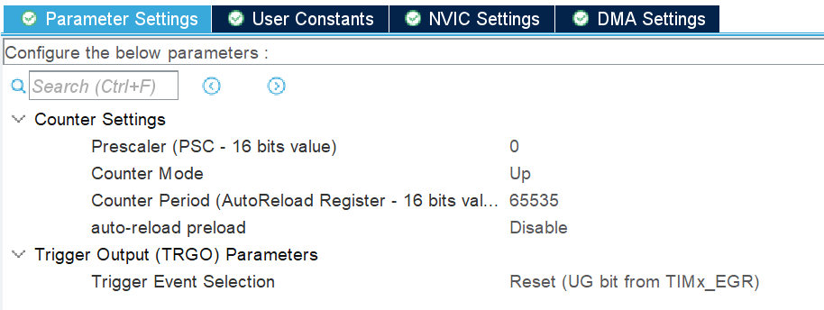
As TIMER6 is connected to APB1, and here we see APB1 timer clocks runs on 90 MHz because of x2 multiplier. Lets adjust the delay, so the minimal delay time would be 1 μs. Default configuration:
Now we need to configure prescaler – it divides the clock by the entered value. We have to have 1 μs delay steps, so the frequency should be:
So the timer should run at 1 MHz and out clock is 90 MHz, so prescaler should divide it by 90. The configuration:
Prescaler value 90-1, why ? Could write 89, would be the same, but easier to see that we are dividing by 90 and prescaler adds 1 to the digit, so we need to subtract 1. I think this is because first value is 0 and it also counts, maybe because you cant divide by zero. Counter period I left maximum, so we can count to 65534 μs if needed. Now we need to write a function, which will make the delay in μs work.
void Delay_in_us (uint16_t us){					// delay function variable us, 16 bit length max
	HAL_TIM_SET_COUNTER(&htim6,0);  			// set the counter value a 0
	while (HAL_TIM_GET_COUNTER(&htim6) < us);   // wait for the counter to count to us set in the variable
}
Function Delay_in_us, with 16b parameter us, first line sets the counter to 0 and second counts till counter reaches the required μs value, so the loop will be processed required period of time, thus processor will not be doing anything, except counting, thus – delay for anything else . Lets toggle the HEATBEAT pin with our new delay function:
while (1) {
/* USER CODE END WHILE */

    HAL_GPIO_WritePin(GPIOA, HEARTBEAT_Pin, pin_state);  // Yellow LED
    pin_state = !pin_state;
    Delay_in_us (1000);

/* USER CODE BEGIN 3 */
}
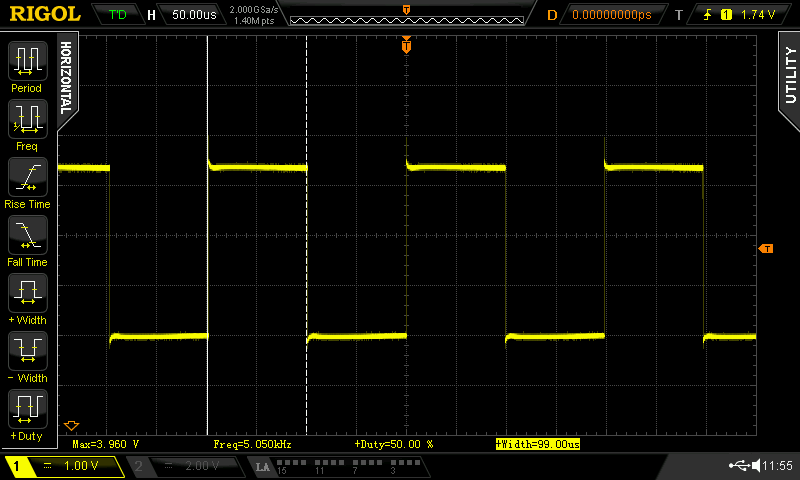
Tested with 10 μs, 100 μs and 1000 μs, the oscilloscope shows:
Seems correct, so the function and timer is working. With bigger values there is slight deviation, for example, instead of 1000 μs we get 990 μs, that’s, probably, because the switching of the pin takes some time, and counter counts 1000 whilst pin switches only 990 times. Not a big tragedy, can adjust that by letting the timer count till 1010 or something. We can troubleshoot that later, when will generate actual timings for the temp sensor. And now we can get back to the sensor initialization, when we need to send specific pulse and wait for sensor response. To do this lets write a simple function:
void DS18B20_init() {
	GPIO_InitTypeDef GPIO_InitStruct = { 0 }; // Setting the DS18B20_Data_Pin as output
	GPIO_InitStruct.Pin = DS18B20_Data_Pin;	// This is already done by the configuration
	GPIO_InitStruct.Mode = GPIO_MODE_OUTPUT_PP;	// in the IOC, but just to train how to do it
	GPIO_InitStruct.Pull = GPIO_NOPULL;			// separately repeating here.
	GPIO_InitStruct.Speed = GPIO_SPEED_FREQ_LOW;
	HAL_GPIO_Init(GPIOA, &GPIO_InitStruct);

	HAL_GPIO_WritePin(GPIOA, DS18B20_Data_Pin, 0);// And as specified in the sensor datasheet pulling the line low for
	Delay_in_us(480);										// 480 us and then

	GPIO_InitStruct.Pin = DS18B20_Data_Pin;	// This time setting the pin as input, to see if
	GPIO_InitStruct.Mode = GPIO_MODE_INPUT;	// sensor responds in timely manner.
	GPIO_InitStruct.Pull = GPIO_PULLUP;	// Enabled the internal pullup, to filter out noise if nothing connected to the pin
	GPIO_InitStruct.Speed = GPIO_SPEED_FREQ_LOW;
	HAL_GPIO_Init(GPIOA, &GPIO_InitStruct);

	Delay_in_us(70);// Datasheet says sensor will respond after 15-60 us, so 70 is a reasonable value

	if (HAL_GPIO_ReadPin(GPIOA, DS18B20_Data_Pin) == 0) {	// After waiting the 70 us checking if we see the low level on the line.

		Delay_in_us(410);// From datasheet, Master RX = 480 us, counting since pulling the pin high, so delay 70us+410us = 480us
		DS18B20_Sensor_present = 1;					// Light up the LED if sensor detected
	}

	else {

		Delay_in_us(410);// From datasheet, Master RX = 480 us, counting since pulling the pin high, so delay 70us+410us = 480us
		DS18B20_Sensor_present = 0;				// Nothing on the LED if sensor not detected
	}

}
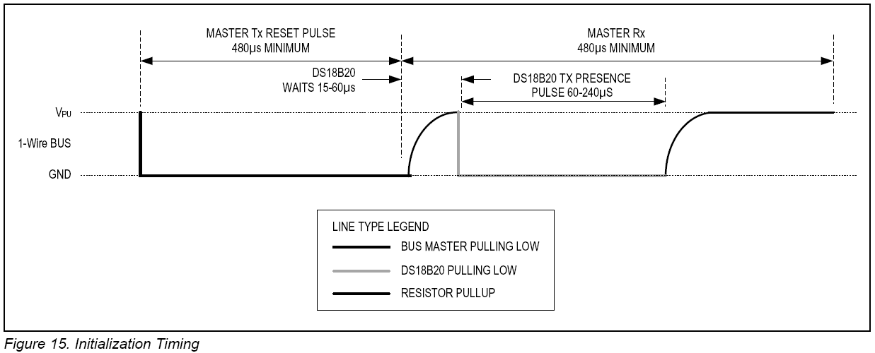
I put comments on each line, so only short explanation – first, we set the pin as output, then set it to low level, logical 0 and wait for specified time. Then we set the pin as input and after some specified time check if we see response from senor. Timing is taken from datasheet:
The only missing time in this graph is the time after which the sensor responds, but its in the text – When the DS18B20 detects this rising edge, it waits 15 μs to 60 μs and then transmits a presence pulse by pulling the 1-Wire bus low for 60 μs to 240 μs. Out development board lights a LED if sensor is detected, but to get even deeper, we want to look what can be seen on the oscilloscope:
Here we can see, that our microprocessor sets the signal low for exactly 480 μs, then it releases the line and pullup resistor brings it back to 3,3 V, then, after 28 μs, the sensor responds by holding line low for 116 μs. So far so good . At this point also renamed the pin_state variable to DS18B20_Sensor_present and a short code for HEARTBEAT, to see if the sensor responds with LED:
	while (1) {
		/* USER CODE END WHILE */
		DS18B20_init();
		HAL_GPIO_WritePin(GPIOA, HEARTBEAT_Pin, DS18B20_Sensor_present);  // Yellow LED
		HAL_Delay(500);
		HAL_GPIO_WritePin(GPIOA, HEARTBEAT_Pin, 0);  // Yellow LED
		HAL_Delay(500);
		/* USER CODE BEGIN 3 */
	}
	/* USER CODE END 3 */
}
Not much here – just run the DS18B20_init() function, it responds with 0 or 1, depending if the sensor is found, and HAL_GPIO_WritePin writes received 0 ir 1 to HEARTBEAT LED, then waits 0,5 s, turns off the LED, waits another 0,5 s and it all starts again, so when sensor connected the LED is blinking, and when sensor disconnected LED is off. This part of code is just to make sure we are on the right path, so it will be removed at the final stage of coding. By the way – if there are multiple DS18B20 sensors on the same bus – they all will respond simultaneously. So response does not mean we have only one sensor, it just means, that we have at least one sensor. Each device on the bus should have some identifier, this applies to DS18B20 too, it has a special 64 bit code, different for all the DS18B20 in the world. For now we will always have only one sensor, so lets just ask it to show the code.
Read Rom [33h]
This command can only be used when there is one slave on the bus. It allows the bus master to read the slave’s 64-bit ROM code without using the Search ROM procedure. If this command is used when there is more than one slave present on the bus, a data collision will occur when all the slaves attempt to respond at the same time.
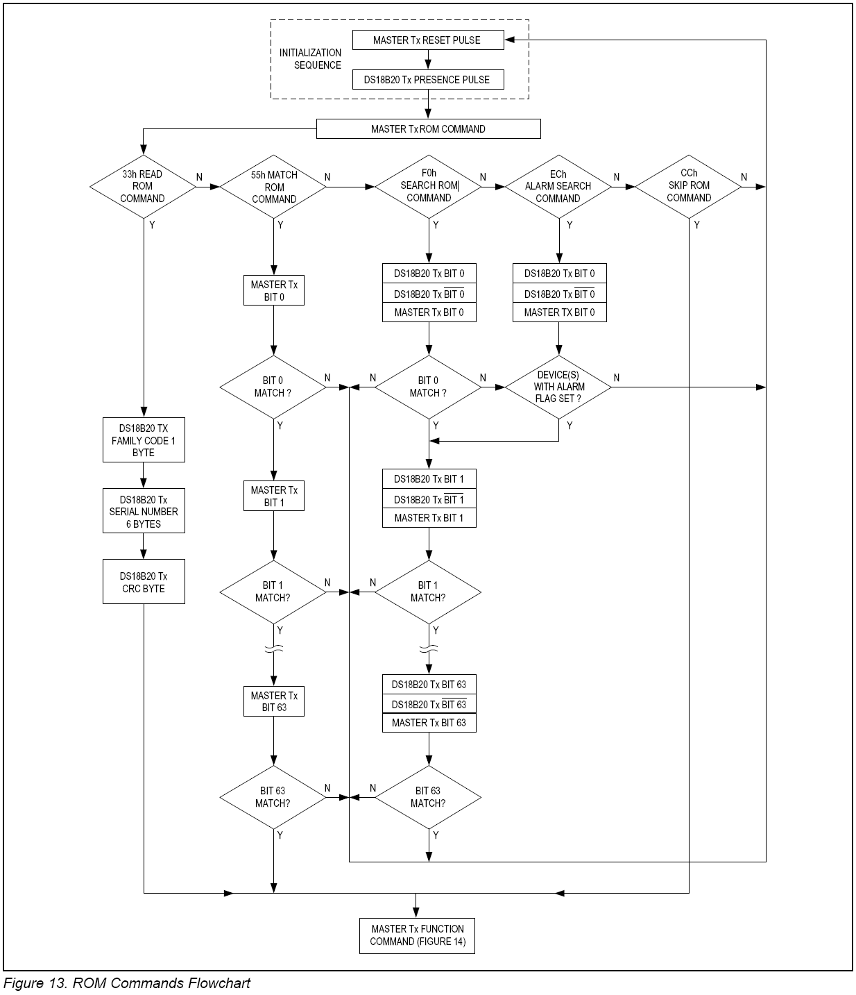
And that means, if we will detect a presence pulse, we will have to ask for ROM code. Naturally, in our test device, we will always have only one device, but later, we might try to make the program universal, so it would search for ROM codes on the bus. The process is in the datasheet, so no need to worry about how to do it:
I will try to make a list of procedures that must be performed in the DS18B20_Read_ROM procedure:
Microprocessor sends initialization sequence (low pulse on bus);
Sensor/-s respond with low pulse;
If the low pulse is detected by microprocessor, it sends READ ROM command, to which the sensor will respond accordingly. The command F33, it must be sent as a bit sequence to the sensors, so it would understand it. Hexadecimal digit F33 in binary is 0011 0011, this is a sequence that needs to be sent to sensors. To write 1 and 0 there is specific diagram:
Means, if microprocessor (MASTER), want to write „0”, it must hold the line low for 15+15+30 μs = 60 μs. The transmitting of „0” must be between 60 μs and 120 μs, lets do 60 μs for start. To write „1” Master must pull the line low for less than 15 μs, let’s say 5 μs and then do nothing for about 60 μs. The datasheet refers to writing „1” and „0” as „Write 1 time slot” and „Write 0 time slot”. And basically explains how to write: To generate a Write 1 time slot, after pulling the 1-Wire bus low, the bus master must release the 1-Wire bus within 15μs. When the bus is released, the 5kΩ pullup resistor will pull the bus high. To generate a Write 0 time slot, after pulling the 1-Wire bus low, the bus master must continue to hold the bus low for the duration of the time slot (at least 60μs and 1μs recovery time between individual write slots). We will have to write another procedure, which will do just that. And writing should be done bit by bit, generating the correct bits and timings for complete byte.
At this point we need to write procedures to write and read information.
void Write_Byte(uint8_t bit_to_send_to_DS18B20) {
	Set_DS18B20_Pin_as_Output();

	for (int i = 0; i < 8; i++) {

		if ((bit_to_send_to_DS18B20 & (1 << i)) != 0) // writing 1 if the bit is high
				{

			Set_DS18B20_Pin_as_Output();
			HAL_GPIO_WritePin(GPIOA, DS18B20_Data_Pin, 0); // writing 0 to the bus
			Delay_in_us(1);  // wait for 1 us
			Set_DS18B20_Pin_as_Input();  // set as input
			Delay_in_us(60);  // wait for 60 us
		}

		else  // writing 0 if the bit is low:
		{

			Set_DS18B20_Pin_as_Output();
			HAL_GPIO_WritePin(GPIOA, DS18B20_Data_Pin, 0); // writing 0 to the bus
			Delay_in_us(60);
			Set_DS18B20_Pin_as_Input();
		}
	}
}
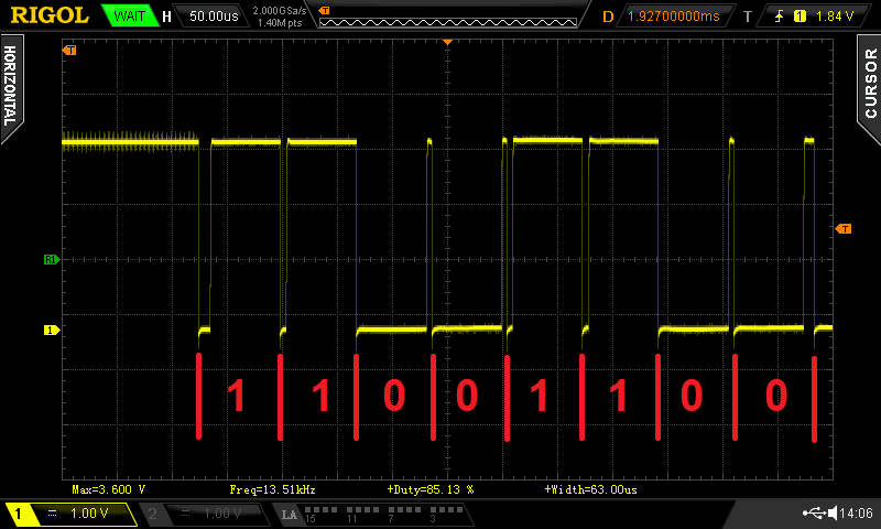
Basically what it does is makes the pin as output, takes our „bit_to_send_to_DS18B20”, which is 0x33 or 0011 0011 and bit by bit, till reaches all 8 bits toggles the output pin accordingly to logical 0 and logical 1. To write 1 we just put pin to 0 for 1 μs and then release it back to pullup, to write 0 we keep pin low for 60 μs and then release it. On the oscilloscope it looks like this:
The DS18B20 responds to this with bunch of data, 64 bits, to be exact. Now we need to read that information.
uint8_t Read_Byte(void) {
	uint8_t byte = 0;

	Set_DS18B20_Pin_as_Input();

	for (int i = 0; i < 8; i++) {
		Set_DS18B20_Pin_as_Output();   // set as output

		HAL_GPIO_WritePin(GPIOA, DS18B20_Data_Pin, 0);  // pull the data pin LOW
		Delay_in_us(1);  // wait for > 1us

		Set_DS18B20_Pin_as_Input();  // set as input
		if (HAL_GPIO_ReadPin(GPIOA, DS18B20_Data_Pin))  // if the pin is HIGH
				{
			byte |= 1 << i;  // read = 1
		}
		Delay_in_us(50);  // wait for 60 us
	}
	return byte;
}
Again, forming the read time slot as described in the datasheet, reading 8 bytes, which is 64 bits and assigning 1 or 0, reacting to the signal length in sensor response. Now we can send commands and read response, so we can try to ask the sensor to tell us its ROM code:
void DS18B20_Read_ROM() {

	if (DS18B20_Sensor_present == 1) {

		Write_Byte(0x33);			// 0x33 = 0b 0011 0011 ; 0xF0 = 0b 1111 0000

		for (int i = 0; i < 8; i++) {
			ROM_address[i] = Read_Byte();
		}
	}
}
First we check if there is a sensor connected, if yes, then ask him 0x33 (to tell the ROM code) and read the answer to ROM_adress. Having ROM address we can quickly check which temperature sensor of the family is connected:
The datasheet says, that first byte will be 0x10 for DS18S20, 0x22 for DS1822 and 0x28 for DS18B20, so we check and write on the LCD what we found.
The PING : PONG on the top comes from TCP/IP protocol, if simple, there if one PC want to check if another PC is connected it asks – PING, and the second PC must reply PONG, so in this case I am writing PING on the LCD when asking for presence pulse from sensor and PONG if the pulse is received. But the sensor is detected, thus LCD indicates what sensor it is. Now I would like to write the ROM address on the LCD, because we already have it. And we have to learn about thing called CASTING, because we need to cast the variable. In our case it is done like this:
const char *ROM_Address = (char*) ROM_address;
What we do is changing the variable type from uint8_t to const char. Why ? Because that damn ST7735 LCD library accepts only const char* pointer (the asterisk * thing). Now if we would write something like that:
The display should indicate ROM address. It should, but it does not – shows only nonsense characters, the first one is „(„. And this leads to the thought, that instead of showing 0x28, hexadecimal digit, LCD shows its ASCII meaning, the „(„. And we are sure the first byte is 0x28, because we already checked it when looked for DS18B20 first byte signature. So before printing we have to set the format of the data. It seems, that display controller takes the 0x28 HEX digit, and, instead of showing it, controller shows the ASCII character with 0x28 code and that is repeated with all bytes in the line, so we get nonsense on display. We need to send formatted data to the LCD… And this can be done using printf family functions, in this case used snprintf().
First made a new variable ROM_AD, to contain the formatted data, which has double the size, because byte 28 in hexadecimal will become two separate bytes, 2 and 8, plus C string must end with „\0”. Strings are actually arrays of characters terminated by a null character „\0”. Actually, there is no „\0” character at the end of a string constant, but he C compiler automatically places the „‘\0” at the end of the string when it initializes the array, so, probably, it would be OK without the „+ 1”, but might cause some warnings during the compilation. So we call the snprintf, tell ir that new data should go to ROM_AD, which will have sizeof(ROM_AD), and next is the formatting – %02X means headecimal digit, with capital letters (x would be non capital letters) and two places, meaning it will write 08 instead of just 8. Repeat it 4 times and then telling the sprintf what data to take, so data from ROM_Address[at location X]. Why only four, instead of 8 ? Because 8 bytes are not fitting into the display, so first I write first 4 bytes, then next 4 bytes in the lower line. And now it looks like this:
And now we have the address of the sensor – 28 3B 1B 1E 0D 00 00 3A. But is this code correct ? We need to check that. Datasheet says, the code consists of:
So the first byte is family code, that we already know, then 6 bytes serial number, then last byte is CRC! And the same datasheet says:
CRC bytes are provided as part of the DS18B20’s 64-bit ROM code and in the 9th byte of the scratchpad memory. The ROM code CRC is calculated from the first 56 bits of the ROM code and is contained in the most significant byte of the ROM.
So actually we can check if the ROM code is correctly received.
The equivalent polynomial function of the CRC (ROM or scratchpad) is:
\[ CRC = {X^8}+{X^5}+{X^4}+1\]
The bus master can re-calculate the CRC and compare it to the CRC values from the DS18B20 using the polynomial generator shown in Figure 11. This circuit consists of a shift register and XOR gates, and the shift register bits are initialized to 0. Starting with the least significant bit of the ROM code or the least significant bit of byte 0 in the scratchpad, one bit at a time should shifted into the shift register. After shifting in the 56th bit from the ROM or the most significant bit of byte 7 from the scratchpad, the polynomial generator will contain the recalculated CRC.
It seems smart and hard, but the function doing the CRC calculation is not that hard:
uint8_t CRC_Calculator(uint8_t *String_to_be_CRCed, uint8_t Len) {
	uint8_t i, dat, fb, rom_bit;
	rom_bit = 0;
	crc = 0;
	do {
		dat = String_to_be_CRCed[rom_bit];
		for (i = 0; i < 8; i++) {
			fb = crc ^ dat;
			fb &= 1;
			crc >>= 1;
			dat >>= 1;
			if (fb == 1)
				crc ^= 0x8c;
		}
		rom_bit++;
	} while (rom_bit < Len);
	return crc;
}
It is described in One Wire protocol and millions of websites, explaining, how to calculate OneWire data CRC. Now we can write some code for DS18B20_Read_ROM() function:
		// CRC check of ROM:
		CRC_Calculator(ROM_address, 7);

		if (crc == ROM_address[7]) {																	// If calculated and received CRC are equal

			snprintf(ROM_Address_to_print, sizeof(ROM_Address_to_print), "%02X", ROM_Address[7]);		// Convert data to printable
			ST7735_WriteString(63, 48, ROM_Address_to_print, Font_7x10, ST7735_GREEN, ST7735_BLUE);		// and print CRC byte in green
			ST7735_WriteString(92, 37, "OK", Font_11x18, ST7735_WHITE, ST7735_BLACK);					// and write "OK"

		}

		else {																							// If calculated and received CRC are not equal

			snprintf(ROM_Address_to_print, sizeof(ROM_Address_to_print), "%02X", ROM_Address[7]);		// convert data to printable
			ST7735_WriteString(63, 48, ROM_Address_to_print, Font_7x10, ST7735_RED, ST7735_BLUE);		// and print CRC byte in red

			char CRC_to_print[sizeof(crc) * 2 + 1];														// Convert calculated
			snprintf(CRC_to_print, sizeof(CRC_to_print), "%02X", crc);									// CRC byte to printable
			ST7735_WriteString(92, 37, CRC_to_print, Font_11x18, ST7735_RED, ST7735_BLACK);				// and write it in red

		}
This part of code will compare received CRC byte with calculated CRC and adjust the information on LCD if CRC matches or not. Next – lets get the sensor scratch pad. From datasheet:
The scratchpad memory contains the 2-byte temperature register that stores the digital output from the temperature sensor. In addition, the scratchpad provides access to the 1-byte upper and lower alarm trigger registers (TH and TL) and the 1-byte configuration register. The configuration register allows the user to set the resolution of the temperature-to-digital conversion to 9, 10, 11, or 12 bits. The TH, TL, and configuration registers are nonvolatile (EEPROM), so they will retain data when the device is powered down.
So this scratchpad thing is the memory where all the information, data and settings are stored in the sensor.
Scratchpad has 9 bytes, at each byte some useful information, except bytes 5, 6 and 7 – those are reserved for some DS18B20 reasons. Last byte is CRC, as if was in ROM data. Lets implement CRC checking for ROM, then read scratchpad, check its CRC and put it all on display.
void DS18B20_Read_ROM() {

	if (DS18B20_Sensor_present == 1) {

		Write_Byte(0x33);												// 0x33 = 0b 0011 0011 ; 0xF0 = 0b 1111 0000

		for (int i = 0; i < 8; i++) {
			ROM_address[i] = Read_Byte();
		}

		ST7735_WriteString(0, 24, "ROM Address", Font_7x10, ST7735_YELLOW, ST7735_BLUE);

		const char *ROM_Address = (char*) ROM_address;

		char ROM_Address_to_print[sizeof(ROM_address) * 2 + 1];

		snprintf(ROM_Address_to_print, sizeof(ROM_Address_to_print), "%02X %02X %02X %02X", ROM_Address[0], ROM_Address[1], ROM_Address[2], ROM_Address[3]);
		ST7735_WriteString(0, 36, ROM_Address_to_print, Font_7x10, ST7735_YELLOW, ST7735_BLUE);
		snprintf(ROM_Address_to_print, sizeof(ROM_Address_to_print), "%02X %02X %02X", ROM_Address[4], ROM_Address[5], ROM_Address[6]);
		ST7735_WriteString(0, 48, ROM_Address_to_print, Font_7x10, ST7735_YELLOW, ST7735_BLUE);

		ST7735_FillRectangle(81, 24, 45, 32, ST7735_BLACK); 			// X, Y, Width, Height
		ST7735_WriteString(82, 25, "ROMCRC", Font_7x10, ST7735_WHITE, ST7735_BLACK);

		// CRC check of ROM:
		CRC_Calculator(ROM_address, 7);

		if (crc == ROM_address[7]) {																	// If calculated and received CRC are equal

			snprintf(ROM_Address_to_print, sizeof(ROM_Address_to_print), "%02X", ROM_Address[7]);		// Convert data to printable
			ST7735_WriteString(63, 48, ROM_Address_to_print, Font_7x10, ST7735_GREEN, ST7735_BLUE);		// and print CRC byte in green
			ST7735_WriteString(92, 37, "OK", Font_11x18, ST7735_WHITE, ST7735_BLACK);					// and write "OK"
			ROM_OK_Flag = 1;
		}

		else {																							// If calculated and received CRC are not equal

			snprintf(ROM_Address_to_print, sizeof(ROM_Address_to_print), "%02X", ROM_Address[7]);		// convert data to printable
			ST7735_WriteString(63, 48, ROM_Address_to_print, Font_7x10, ST7735_RED, ST7735_BLUE);		// and print CRC byte in red

			char CRC_to_print[sizeof(crc) * 2 + 1];														// Convert calculated
			snprintf(CRC_to_print, sizeof(CRC_to_print), "%02X", crc);									// CRC byte to printable
			ST7735_WriteString(92, 37, CRC_to_print, Font_11x18, ST7735_RED, ST7735_BLACK);				// and write it in red
			ROM_OK_Flag = 0;
		}

	}

	else {
		ST7735_WriteString(35, 0, "ERROR1", Font_7x10, ST7735_YELLOW, ST7735_BLUE);
	}

}
And for the scratchpad:
void DS18B20_Read_Scratchpad() {

	DS18B20_init();

	if (DS18B20_Sensor_present == 1) {
		if (ROM_OK_Flag == 1) {
			ST7735_WriteString(35, 0, "PONG", Font_7x10, ST7735_YELLOW, ST7735_BLUE);

			Write_Byte(0x55);																			// Match ROM command [0x55]
			for (int i = 0; i < 8; i++) {																// Send previously detected
				Write_Byte(ROM_address[i]);																	// ROM, all 8 bytes
			}
			Write_Byte(0x44);																			//Convert Temperature [44h] to update the scratchpad

			DS18B20_init();

			if (DS18B20_Sensor_present == 1) {
				ST7735_WriteString(35, 0, "PONG", Font_7x10, ST7735_YELLOW, ST7735_BLUE);

				Write_Byte(0x55);																		// Match ROM command [0x55]
				for (int i = 0; i < 8; i++) {															// Send previously detected
					Write_Byte(ROM_address[i]);																// ROM, all 8 bytes
				}
				Write_Byte(0xBE);																		// Read scratchpad command

				for (uint8_t i = 0; i < 9; i++) {
					Scratchpad[i] = Read_Byte();
				}

				ST7735_WriteString(0, 60, "Scratchpad:", Font_7x10, ST7735_YELLOW, ST7735_BLUE);

				Cfg_Reg = Scratchpad[3];

				const char *ScratchPad = (char*) Scratchpad;

				char ScratchPad_to_print[sizeof(Scratchpad) * 2 + 1];

				snprintf(ScratchPad_to_print, sizeof(ScratchPad_to_print), "%02X %02X", ScratchPad[0], ScratchPad[1]);
				ST7735_WriteString(0, 72, ScratchPad_to_print, Font_7x10, ST7735_RED, ST7735_BLUE);

				snprintf(ScratchPad_to_print, sizeof(ScratchPad_to_print), "%02X %02X", ScratchPad[2], ScratchPad[3]);
				ST7735_WriteString(41, 72, ScratchPad_to_print, Font_7x10, ST7735_YELLOW, ST7735_BLUE);

				snprintf(ScratchPad_to_print, sizeof(ScratchPad_to_print), "%02X", ScratchPad[4]);
				ST7735_WriteString(0, 84, ScratchPad_to_print, Font_7x10, ST7735_YELLOW, ST7735_BLUE);

				snprintf(ScratchPad_to_print, sizeof(ScratchPad_to_print), "%02X %02X %02X", ScratchPad[5], ScratchPad[6], ScratchPad[7]);
				ST7735_WriteString(21, 84, ScratchPad_to_print, Font_7x10, ST7735_BLACK, ST7735_BLUE);

				ST7735_FillRectangle(81, 61, 45, 42, ST7735_BLACK); 												// X, Y, Width, Height
				ST7735_WriteString(82, 62, "SCRPAD", Font_7x10, ST7735_WHITE, ST7735_BLACK);
				ST7735_WriteString(92, 74, "CRC", Font_7x10, ST7735_WHITE, ST7735_BLACK);

				CRC_Calculator(Scratchpad, 8);

				if (crc == Scratchpad[8]) {																		// If calculated and received CRC are equal

					snprintf(ScratchPad_to_print, sizeof(ScratchPad_to_print), "%02X", Scratchpad[8]);			// Convert data to printable
					ST7735_WriteString(0, 96, ScratchPad_to_print, Font_7x10, ST7735_GREEN, ST7735_BLUE);		// and print CRC byte in green
					ST7735_WriteString(92, 84, "OK", Font_11x18, ST7735_WHITE, ST7735_BLACK);					// and write "OK"

				} else {																						// If calculated and received CRC are not equal

					snprintf(ScratchPad_to_print, sizeof(ScratchPad_to_print), "%02X", Scratchpad[8]);			// convert data to printable
					ST7735_WriteString(0, 96, ScratchPad_to_print, Font_7x10, ST7735_RED, ST7735_BLUE);			// and print CRC byte in red

					char CRC_to_print[sizeof(crc) * 2 + 1];														// Convert calculated
					snprintf(CRC_to_print, sizeof(CRC_to_print), "%02X", crc);									// CRC byte to printable
					ST7735_WriteString(92, 84, CRC_to_print, Font_11x18, ST7735_RED, ST7735_BLACK);				// and write it in red
				}

			} else {
				ST7735_WriteString(35, 0, "ERROR4", Font_7x10, ST7735_YELLOW, ST7735_BLUE);
			}

		} else {
			ST7735_WriteString(35, 0, "ERROR3", Font_7x10, ST7735_YELLOW, ST7735_BLUE);
		}

	} else {
		ST7735_WriteString(35, 0, "ERROR2", Font_7x10, ST7735_YELLOW, ST7735_BLUE);
	}
}
Notice, that I also made a small upgrade – writing byte 0x55, which asks the DS18B20 to respond only if its ROM address is a match. Its not required for one sensor on line, but we are learning to manage the sensors, right, so maybe in the future we will need to add more sensors and here were are – snippet already prepared . Ok, now we have both ROM and scratchpad. ROM we already analyzed, but what can we get from the scratchpad ?
Byte 0 and byte 1 of the scratchpad contain the LSB and the MSB of the temperature register, respectively. These bytes are read-only. Bytes 2 and 3 provide access to TH and TL registers. Byte 4 contains the configuration register data, which is explained in detail in the Configuration Register section. Bytes 5, 6, and 7 are reserved for internal use by the device and cannot be overwritten. Byte 8 of the scratchpad is read-only and contains the CRC code for bytes 0 through 7 of the scratchpad. The DS18B20 generates this CRC using the method described in the CRC Generation section.
So, byte 0 and byte 1 are clear – stored temperature, bytes 2 and 3 – register controls, not sure if I will do anything with them. Byte 4 – configuration register, this might be interesting. We already have it in the scratchpad reading function, lets just write it in binary form, to have all the bits and easy understanding of the settings there.
void DS18B20_Decode_Config_Register() {

	if (DS18B20_Sensor_present == 1) {
		if (ROM_OK_Flag == 1) {

			char Config_Register_to_print[sizeof(Cfg_Reg) * 2 + 1];

			snprintf(Config_Register_to_print, sizeof(Config_Register_to_print), "%02X", Cfg_Reg);

			char hex2bin[8] = "";

			for (int i = 0; i < 2; i++) {

				switch (Config_Register_to_print[i]) {
				case '0':
					strcat(hex2bin, "0000");
					break;
				case '1':
					strcat(hex2bin, "0001");
					break;
				case '2':
					strcat(hex2bin, "0010");
					break;
				case '3':
					strcat(hex2bin, "0011");
					break;
				case '4':
					strcat(hex2bin, "0100");
					break;
				case '5':
					strcat(hex2bin, "0101");
					break;
				case '6':
					strcat(hex2bin, "0110");
					break;
				case '7':
					strcat(hex2bin, "0111");
					break;
				case '8':
					strcat(hex2bin, "1000");
					break;
				case '9':
					strcat(hex2bin, "1001");
					break;
				case 'a':
				case 'A':
					strcat(hex2bin, "1010");
					break;
				case 'b':
				case 'B':
					strcat(hex2bin, "1011");
					break;
				case 'c':
				case 'C':
					strcat(hex2bin, "1100");
					break;
				case 'd':
				case 'D':
					strcat(hex2bin, "1101");
					break;
				case 'e':
				case 'E':
					strcat(hex2bin, "1110");
					break;
				case 'f':
				case 'F':
					strcat(hex2bin, "1111");
					break;
				default:
					printf("Invalid hexadecimal input.");
				}
			}
			ST7735_WriteString(0, 108, "CFG REG: ", Font_7x10, ST7735_YELLOW, ST7735_BLUE);
			ST7735_WriteString(56, 108, hex2bin, Font_7x10, ST7735_YELLOW, ST7735_BLUE);
		}
	}
}
Here we take the register byte, condition it with snprintf() and two times run the cycle to process both digits to binary form, strcat() function joins them together, so we get a row of bits and print them on LCD in hex2bin variable. At this point the LCD is almost full of information .
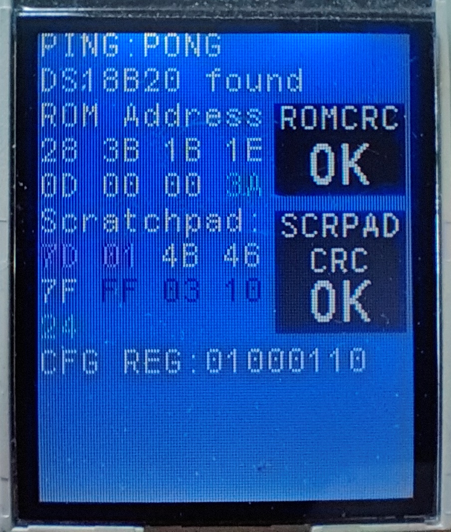
All the lines explained:
The PING : PONG presence check
Temperature sensor detection from ROM (can be DS18S20, DS1822 or DS18B20)
On the left side ROM address in HEX (28 3B 1B 1E 0D 00 00 3A), on the right side ROM CRC check result. If CRC (3A) is OK, then last read byte is green, if not the same the read last byte (3A) will be marked red, and in the black CRC ROM area calculated CRC will be displayed, also in red, so we can visibly compare them.
On the left scratchpad data in HEX (7D 01 4B 46 7F FF 03 10 24). Similarly, on the right side in black area scratchpad CRC check result. All the checking is the same as ROM, so read CRC byte is green if OK, and red if not OK and calculated CRC will be written instead of OK.
Configuration register in binary form, 0x46 = 0100 0110.
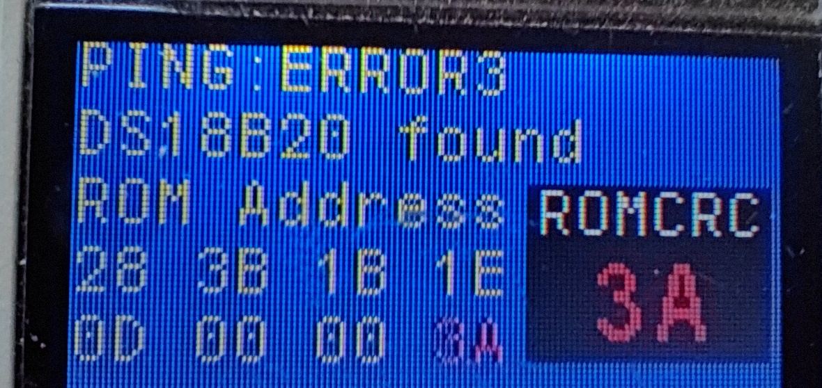
Adjusted the code a bit, so it would indicate the fault in CRC (but CRC is good, so the digits are the same):
PING also reports, that we have ERROR3. We might want to write some more text, instead of ERROR3, to have a nice error handler, but not necessary.
The configuration register in our case has 0100 0110, so what does it mean ? Lets look at the datasheet:
Byte 4 of the scratchpad memory contains the configuration register, which is organized as illustrated in Figure 10. The user can set the conversion resolution of the DS18B20 using the R0 and R1 bits in this register as shown in Table. The power-up default of these bits is R0 = 1 and R1 = 1 (12-bit resolution). Note that there is a direct tradeoff between resolution and conversion time. Bit 7 and bits 0 to 4 in the configuration register are reserved for internal use by the device and cannot be overwritten.
So its clear, that bits 0, 1, 2, 3, 4, 7 are not used, only two bits, 5 and 6 are used, to set the conversion resolution = temperature measurement resolution. Lets quickly write the simple code to decode the resolution:
Its really very simple, first we use bitwise operation on Cfg_Reg, which is our configuration register, with value 0100 0110. We make a bitwise right operation, so the bits are scrolled right by 5 places:
0100 0110 >> 5 = 0000 0010
All the bits are pushed to the right, dropping them (dropped bits in red), and new zeros added (the yellow zeros) from the left side. But 0000 0010 = 10, so we have filtered out the required bits from the byte. This will only work, because in DS18B20 the first bit will always be 0. Its its 1, for example 1100 0110, first we would do bitwise left 1, so the result would drop the first bit and add 0 on the end, 1000 1100, then we would just bitwise right 6 places, the result would be 1000 1100, red dropped, 0000 0010 = 10. And now its easy to find out the resolution:
In our case its 10, so 11 bits resolution, conversion time 375 ms.
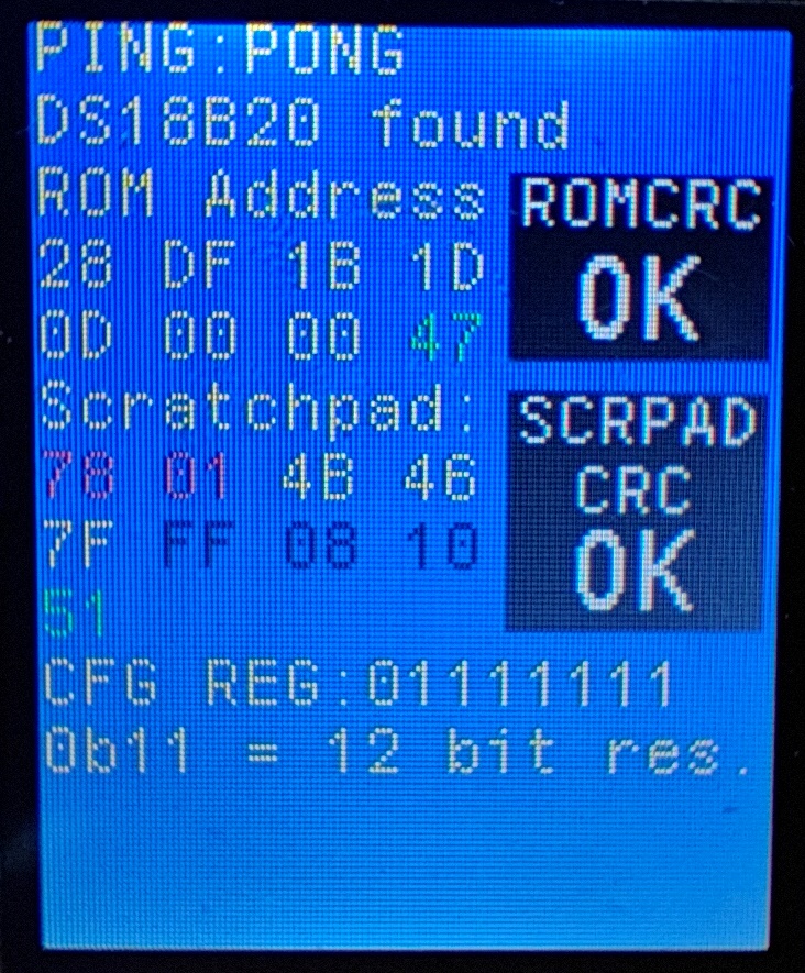
At this point, I hope, you, like me, noticed, that configuration register cannot be 0100 0110. Because in the picture with register decoding bits are like this – 0 R1 R0 1 1 1 1 1. The red bits are mandatory and should be the same. And when I realized that – thought, something must be wrong with the code. Indeed, found an error – in the DS18B20_Read_Scratchpad() procedure incorrectly picked the configuration bit Cfg_Reg = Scratchpad[3], should be Cfg_Reg = Scratchpad[4]. With correct byte decoded, the view is a bit different:
And now we have the correct CFG register, default after every power up – 0111 1111, 12 bits resolution. Lets try to write a new resolution setting. To do that, we must write to DS18B20 scratchpad:
void DS18B20_Write_Scratchpad() {

	if (DS18B20_Sensor_present == 1) {
		if (ROM_OK_Flag == 1) {
			DS18B20_init();
			ST7735_WriteString(35, 0, "PONG", Font_7x10, ST7735_YELLOW, ST7735_BLUE);

			Write_Byte(0x55);																			// Match ROM command [0x55]
			for (int i = 0; i < 8; i++) {																// Send previously detected
				Write_Byte(ROM_address[i]);																// ROM, all 8 bytes
			}

			Write_Byte(0x4E);    																		//Write Scratchpad command
			Write_Byte(0xFF);    																		//Set TH alarm value 0xFF = +125
			Write_Byte(0x7F);    																		//Set TL alarm value 0x7F = -55C
			Write_Byte(0x7F);    													//Set resolution, 9 bit = 0x1F, 10 bit = 0x3F, 11 bit = 0x5F, 12 bit = 0x7F

		}
	}
}
Here, after checking that sensor is still connected we send a Match ROM command, so only the required sensor would respond (again, not necessary if only one sensor is on the network), then we send the ROM address. Next command Write Scratchpad (0x4E), set TH and TL values (it seems, that those must be present) and last command is to set the resolution. In the code there is no part, responding to hardware changes to set the resolution, for example, high level on input PC13 would turn on 12 bit resolution, on input PC14 would set 11 bit resolution, etc. – all this is changed only in the main program, so you would have to add some lines if hardware switching is required. After the configuration, last thing we can do it the main thing – decode the temperature:
void DS18B20_Decode_Temperature() {

	if (DS18B20_Sensor_present == 1) {
		if (ROM_OK_Flag == 1) {

			uint16_t Byte0_LSB = (Scratchpad[0]);
			uint16_t Byte1_MSB = (Scratchpad[1]);
			char Byte0_LSB_ITOA[16];
			char Byte1_MSB_ITOA[16];
			itoa(Byte0_LSB, Byte0_LSB_ITOA, 16);
			itoa(Byte1_MSB, Byte1_MSB_ITOA, 16);
			ST7735_WriteString(0, 144, Byte1_MSB_ITOA, Font_7x10, ST7735_YELLOW, ST7735_BLACK);
			ST7735_WriteString(14, 144, ":", Font_7x10, ST7735_YELLOW, ST7735_BLACK);
			ST7735_WriteString(21, 144, Byte0_LSB_ITOA, Font_7x10, ST7735_YELLOW, ST7735_BLACK);

			if ((Scratchpad[1] >> 4) == 0b0000) {

				switch (Cfg_Reg) {
				case 0b01111111:;																	// 12 bit resolution

					uint16_t Positive_temp = ((Scratchpad[1]<<8) + Scratchpad[0]);					// Scratchpad[1]<<8 makes from 0000 000X to X 0000 0000
					float Positive_temp_float = (Positive_temp/16.0);								// Calculating the temperature
					char Positive_temp_FTOC[16];													// then + Scratchpad[0] put bits into it X YYYY YYYY
					sprintf(Positive_temp_FTOC, "T:+%.4fC",Positive_temp_float);						// thus making one complete binary number, which must be /16 for 12 bit resolution
					ST7735_WriteString(49, 144, Positive_temp_FTOC, Font_7x10, ST7735_YELLOW, ST7735_BLUE); // Writing the Positive Temperature Float TO Char value to LCD

					break;

				case 0b01011111:																	// 11 bit resolution

					break;

				case 0b00111111:																	// 10 bit resolution

					break;

				case 0b00011111:																	// 9 bit resolution

					break;

				default:

					ST7735_WriteString(35, 0, "ERROR7", Font_7x10, ST7735_YELLOW, ST7735_BLUE);

					break;
				}

			} else {

				if ((Scratchpad[1] >> 4) == 0b1111) {
					ST7735_WriteString(77, 144, "-", Font_7x10, ST7735_YELLOW, ST7735_BLUE);
				}

			}

		}

	}
}
Again, first checking if the sensor is still present, then picking the required bytes from scratchpad (byte 0 and byte 1) and writing those two bytes on display. Here, to show a bit different technique I used itoa() function, instead of sprintf(). There are some advantages and disadvantages – itoa() is lightweight and fast, but compared to sprintf() it has no formatting and configuration capabilities. Next with if() statement we just check if the temperature is below 0 °C or above 0 °C. Let’ look at the example temperatures table in datasheet:
We can clearly see, that below 0 °C temperatures has ones in the first byte and first bit of the second byte:
-55 °C = 1111 1100 1001 0000
IT would be wise to do first – check if there are „1” or „0” and make two different calculations, because for above 0 °C its pretty straight forward, but for below 0 °C we will need to convert the value, but its also described in the datasheet. So there should be two conditions for the if() statement:
(Scratchpad[1] >> 4) == 0b0000) and (Scratchpad[1] >> 4) == 0b1111), which makes right bitshift of the byte 1 of the scratchpad. What it does is it takes byte 1 of the scratch pad (-55 °C = 1111 1100 1001 0000) and shits it to the right by 4 places, so dropping the right 4 bits (1100) and leaves us with only left 4 bits (1111). And the logic is simple – if its 0000 then temperature is above zero degrees, if its 1111 – temperature is below zero. In the example we calculate only positive temperatures (negative temperature section is not yet coded). The calculation is done by this line:
float Positive_temp_float = (Positive_temp/16.0);
Different approaches can be used to have a floating variable, but because or processor supports floating point calculation (internal floating point unit – FPU), we just enable „-u _printf_float” in the „Project Properties > C/C++ Build > Settings > Tool Settings” and it does the job. Notice, that 16 has a zero (16.0) and to make it floating point variable. Next we configure the variable for the LCD:
T:+%.4fC is the formatting, meaning we write T:+ on display, then %f means that it will be floating point digit, C is just a letter C, to mark Celsius degrees. The .4 means that we format the floating point digit to have 4 digits after comma (.), otherwise we would have 6 digits and last two would always be 0.
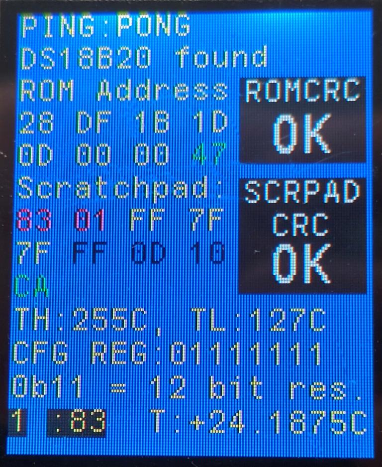
But now we have this view on LCD:
Under the scratchpad data we have separate indication of TH and TL – high and low alarm setting (2 and 3 bytes of the scratch pad), which is not correct, by the way, need to finalize the decoding, for proper indication. Next we have configuration register (3 byte of the scratchpad) in binary format, just to see how bits are changed, when setting different resolutions (because its the only thing that can be changed/configured). Then after checking the configuration register bits, we indicate the current setting 0b11, which means 12 bit resolution. Below, in black background, we have bytes 1 and 0 of the scratchpad, its where the temperature reading is saved and to the right of those two bytes we have decoded temperature, at the moment – positive only, still need to code two’s complement calculation or conversion for the negative temperatures.
The code is „dirty” and not yet completed, but that is done on purpose – dirty, not optimized code will give more insights and information about how it works, allowing to filter out unnecessary functions and making it easy to complete to the fully working program, at the sate time trying different approaches to complete some task.
Eilinis, nieko neišskirtinas kinas, tokie maitinimo šaltiniai štampuojami kažkurioje gamykloje, keičiamas tik užsakovo lipdukas, todėl šitos piguvos yra visas zooparkas.
Manson gamintojo:
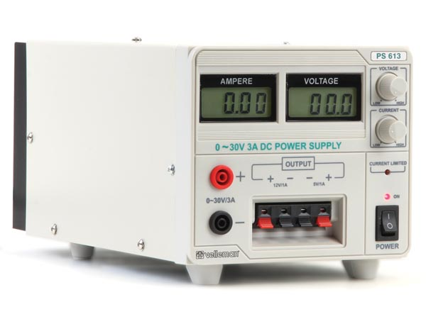
Velleman PS-613:
Dick Smith Electronics:
Circuit Test PSA-2530D:
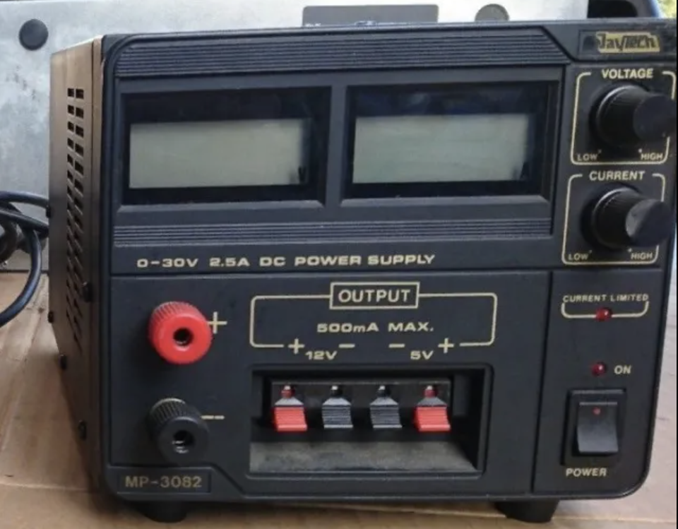
Jaytech MP-3082:
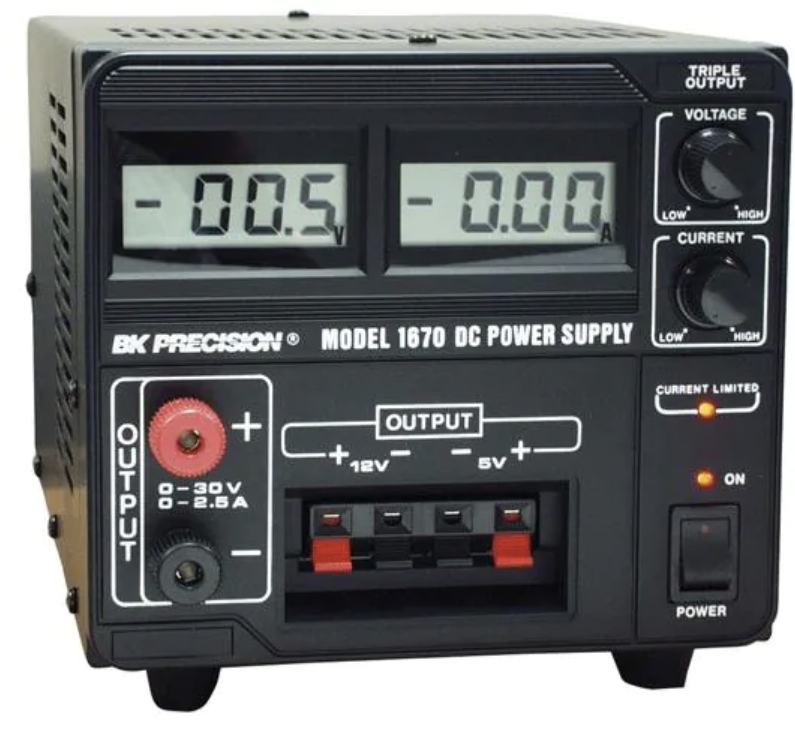
Taigi, visur tas pats kiniškas klonas, iš kurio nereiktų tikėtis kažko rimto. Beje, yra ir 5A išėjimo versija, viskas tas pats, tik tranzistoriai galingesni. Ir spėju, kad visa šita gauja yra vieno gero BK Precission maitinimo šaltinio klonai.
BK Precission neturiu, tai nepasakysiu ar viduriai tokie patys. O dabar pereikime prie remonto. Gedimas – ienas iš LCD ekraniukų nustojo rodyti, tiksliau rodo kokias tai nesąmones srovės indikacijos ekranėlyje.
Pradžiai ardom, pakeliui žiūrėdami kas čia per žvėris.
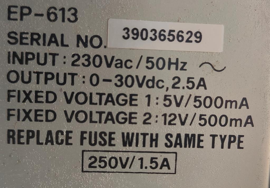
Taigi, turime ir specifikaciją, nieko įspūdingo, 30V 2,5A reguliuojamas ir 5V bet 12V 500 mA nereguliuojamas išėjimai. 12V išėjimo teigiamas kontaktas be fiksatoriaus…
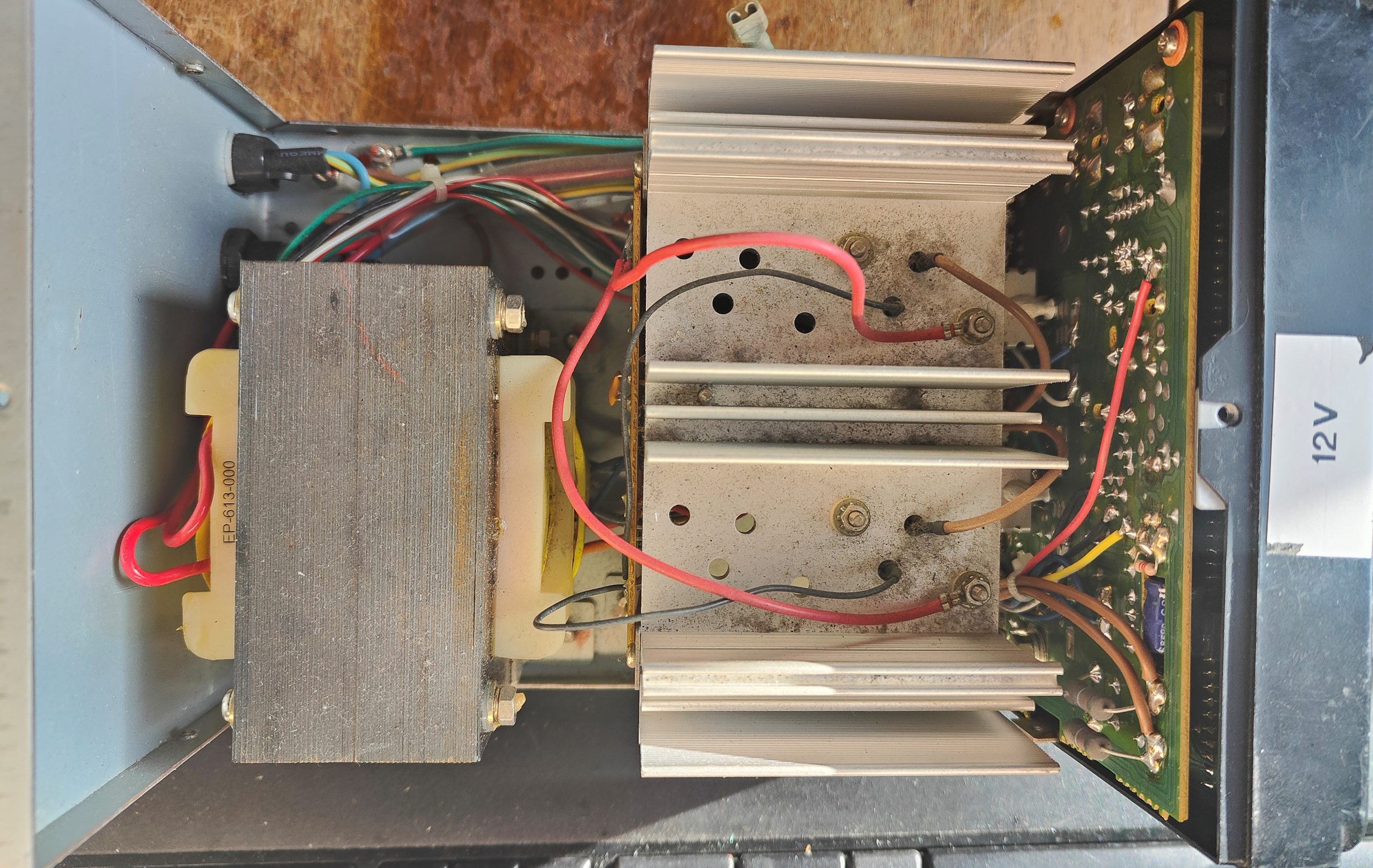
Vaizdas iš viršaus, transformatoriaus markiruotė EP-613-000, nieko informatyvaus, pasyvus aušinimas išėjimo tranzistoriams, matosi, kad yra tuščių montavimo skylių – matomai 5A versijoje ten gyvena papildomi tranzistoriai, lygiagrečiai esamiems.
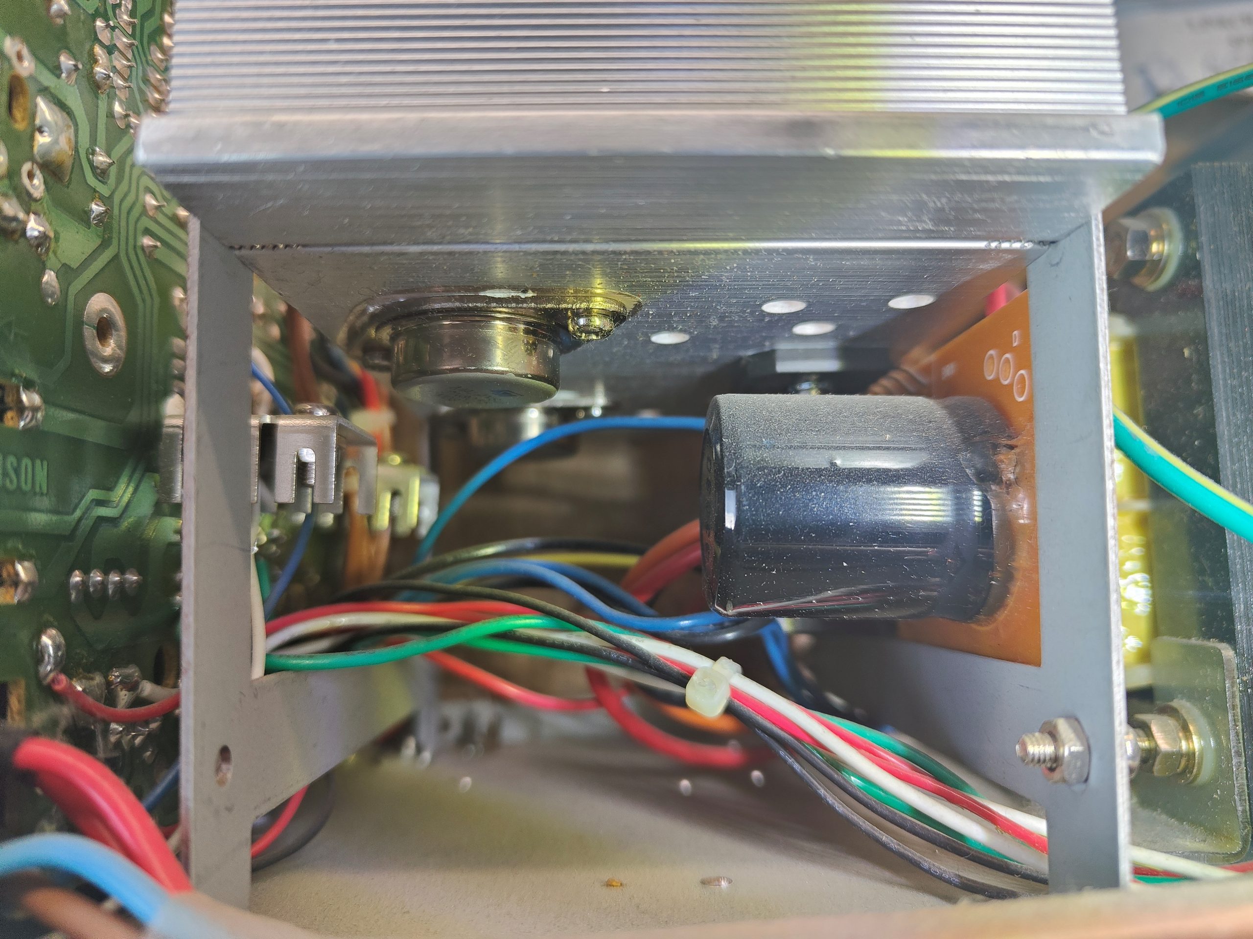
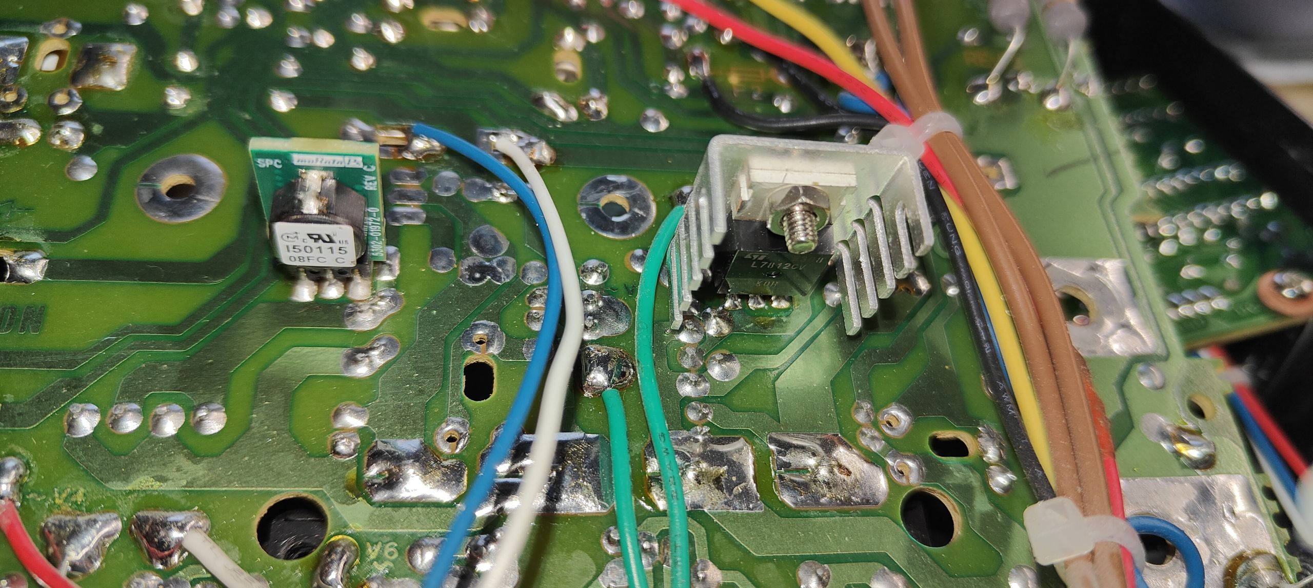
Vaizdelis po radiatoriumi. Taigi, pora ST gamybos tranzistorių 2N3055, kairiau matosi pora linijinių stabilizatorių su radiatoriukais, gaminančių 5V ir 12V, dešinėje šioks toks kondensatrius, tiltelis ir…
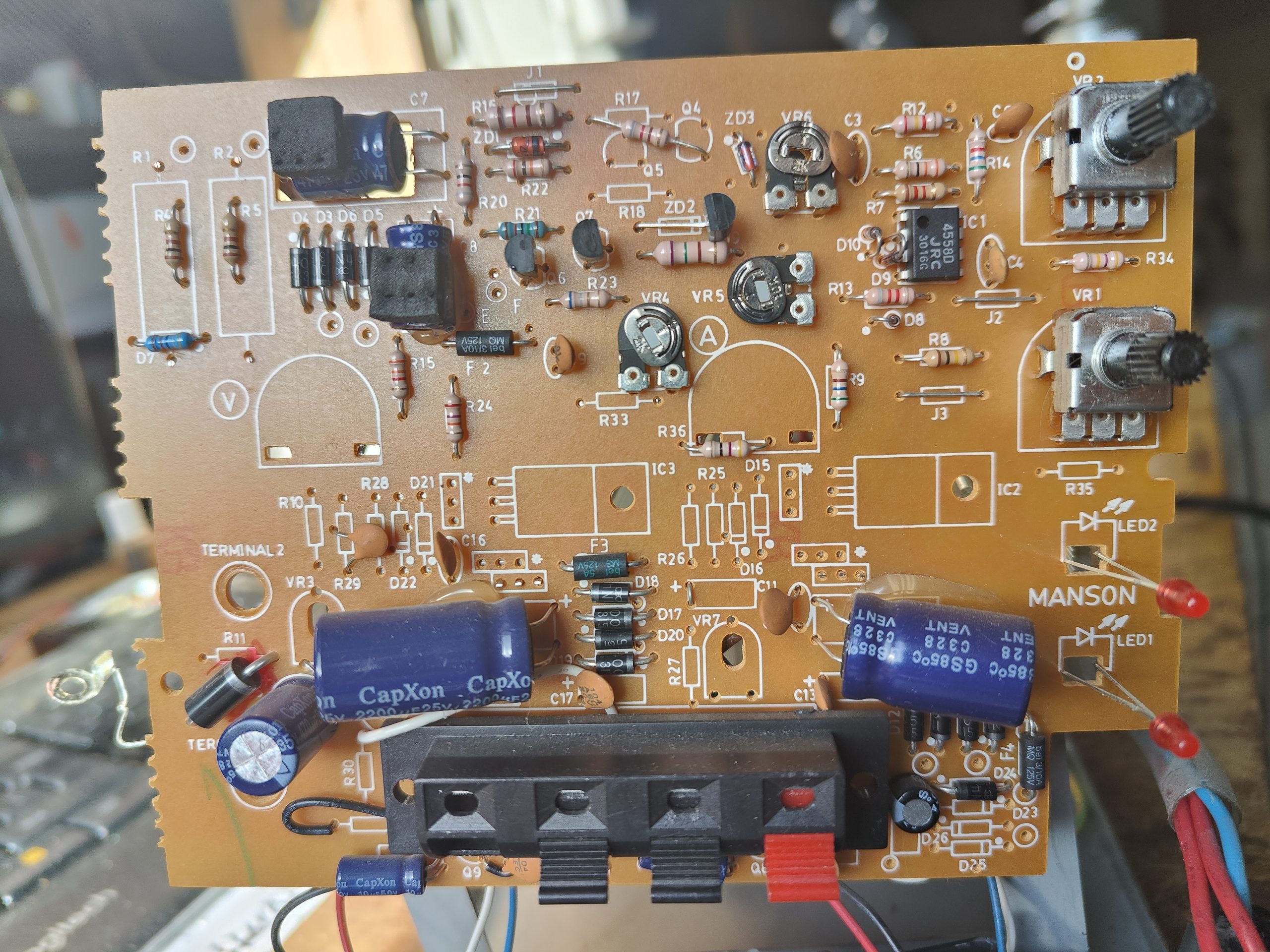
Pereiname prie priekinės PCB, čia truputį daugiau elektronikos, bet irgi nieko įspūdingo. Žalioje pusėje tie patys du stabilizatoriai, turbūt LM7805 ir LM7812. Plokštė universali, todėl rudoje pusėje matosi ir montavimo vietos rodykliniams indikatoriams bei vietos kitoms detalėms. Litavimo kokybė tai tokia… Kinietiška . Žalioje pusėje dar porelė didelių rezistorių – srovės matavimo šuntai, pilkoje visokia neįdomi analoginė smulkmė ir viena mikroschema – JRC gamybos 4558D operacinukas, jeigu kartais reiks keisti, dėsiu kilmingesnį, Texas Instruments RC4558. Ir trys paderinimo rezistoriai, reiks pažiūrėti, kam jie skirti. Numontavus visą plokšte pasimato ir displėjaus moduliukai.
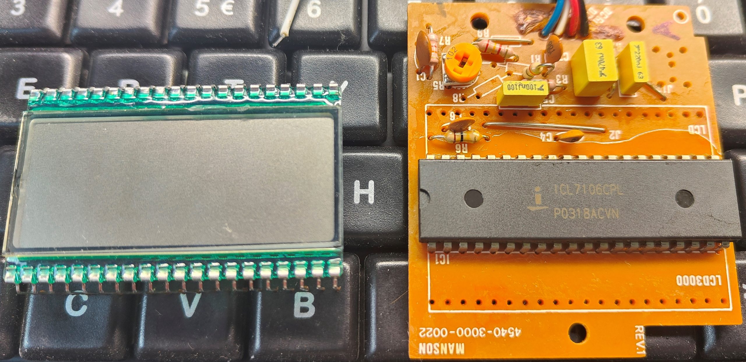
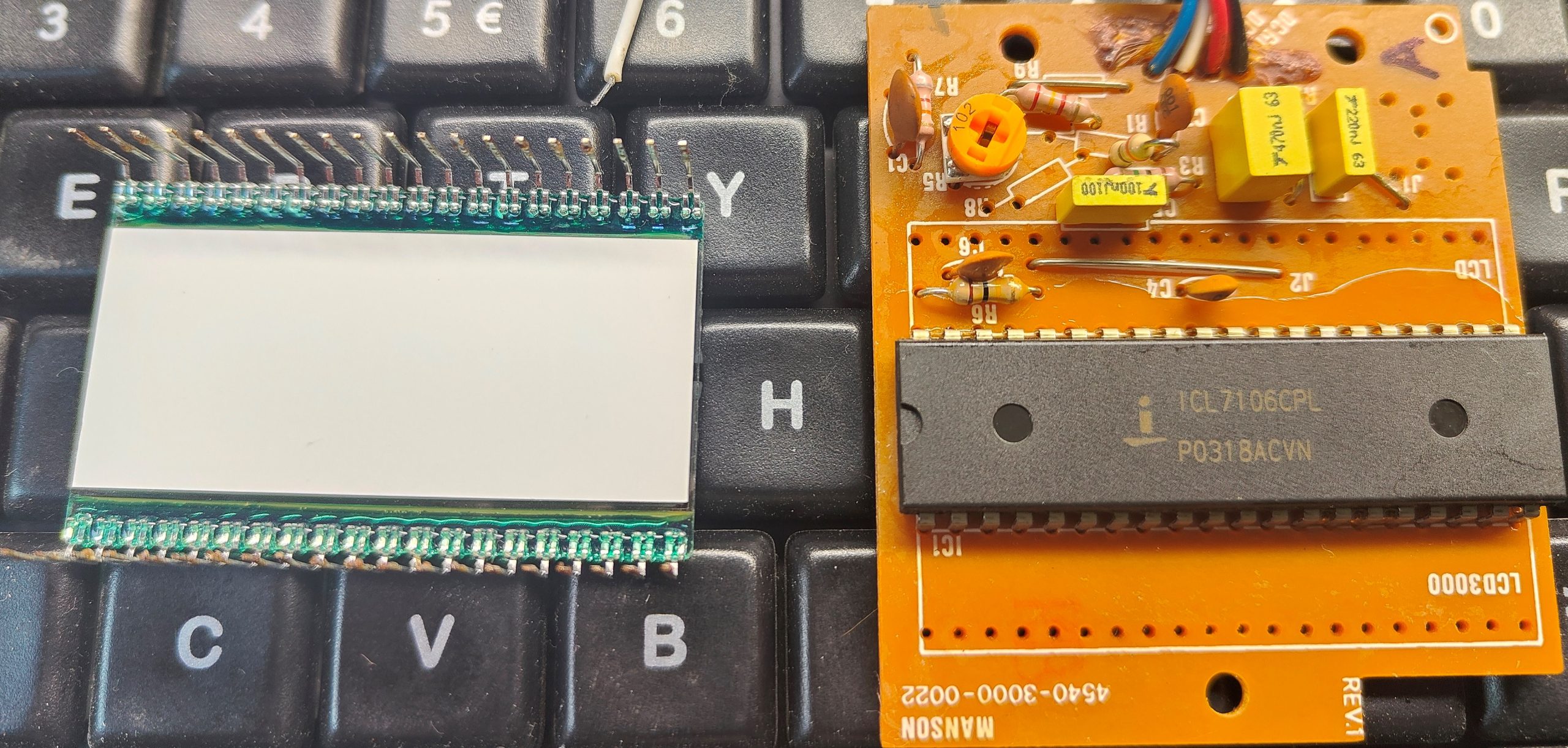
Aha, atskiri moduliukai, truputį skirtingi V ir A indikavimui, su savo paderinimo rezistoriais. Modulių markiruotė Manson 4540-3000-0022 REV. 1 visiškai neinformatyvi, bet kai ką galima išmąstyti. LCD 3,5 skaičiaus formato, t. y., gali rodyti 1888, dar gali rodyti LOBAT ir + bei -, po LCD akivaizdžiai gyvena valdiklis. LOBAT ir + nenaudojami. LCD dydis standartinis, 50,8 x 30,5 mm, maitinimas 5V, atspindinčio (reflective) tipo, skaičiaus dydis 12,7 mm. O kodėl gi displėjukas rodo neteisingai ? Manyčiau kaltas visų pirma valdiklis, teks nuimti displėjuką, kad patikrinti kokia mikroschema jį valdo. Prie to pačio – vien valdiklis ne visada būna kaltas. Tokie LCD nors ir jautrūs, bet tuo pačiu gan atsparūs išorės poveikiui, o vat jeigu valdiklis pradeda juos šerti nuolatine įtampa vietoje kintamos – atsiranda toks išdegimo efektas ir valdymo artefaktai. Taigi keisti reikės abu – ir valdiklį ir LCD.
Štai ir valdiklis, Intersil ICL7106CPL – dedikuotas LCD valdikliukas. LCD be jokių užrašų abejose pusėse. Numontuojam…
Nesitikėjau, bet pavyko gauti tikrą, originalų Intersilo ICL7106CPL valdiklį ! Todėl iš karto jį galėjau ir sumontuoti:
Jeigu kartais originalių valdiklių gauti nepavyks – dėkite analogą Maxim Integrated ICL7106CPL+, bet jokių būdu ne iš AliExpress ir panašių kontorų – bus padirbiniai. Turėtų sueiti kaip tiesioginis pakaitalas, be jokių perdarymų:
O štai ir jungimo schema:
Ir dabar jau aišku kas per paderinimo rezistoriai and displėjaus modulių – sudaromas daliklis REF HI ir REF LO, atraminėms matavimo įtampoms. Mikroschemoje sumontuoti trys 7 segmentų valdikliai, greičiausiai BCD (binary coded decimal), kurie mūsų atveju bus biškį pasprogę. Tūkstančių indikacija, panašu, kad veikia gerai, bet gal todėl, kad neturi savo BCD dekoderio, valdymas iš karto iš skaitliuko, tik per buferį.
Kol tiek, LCD užsakytas, jeigu pasitvirtins tinkamumas pridėsiu markę.
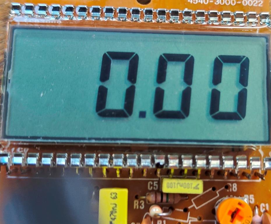
Dislėjus gautas ir įlituotas, keista, bet netgi veikia.
Displėjaus markė – Varitronix VI-302-DP-RC-S. Vienintelis minusas – kojos per trumpos, teko prailginti, pasinaudojant senojo displėjaus kojomis. Pirma įlitavau seną displėjų, tada jį nukirpau ir prie likusių ant PCB kontaktų prilitavau naują displėjų.
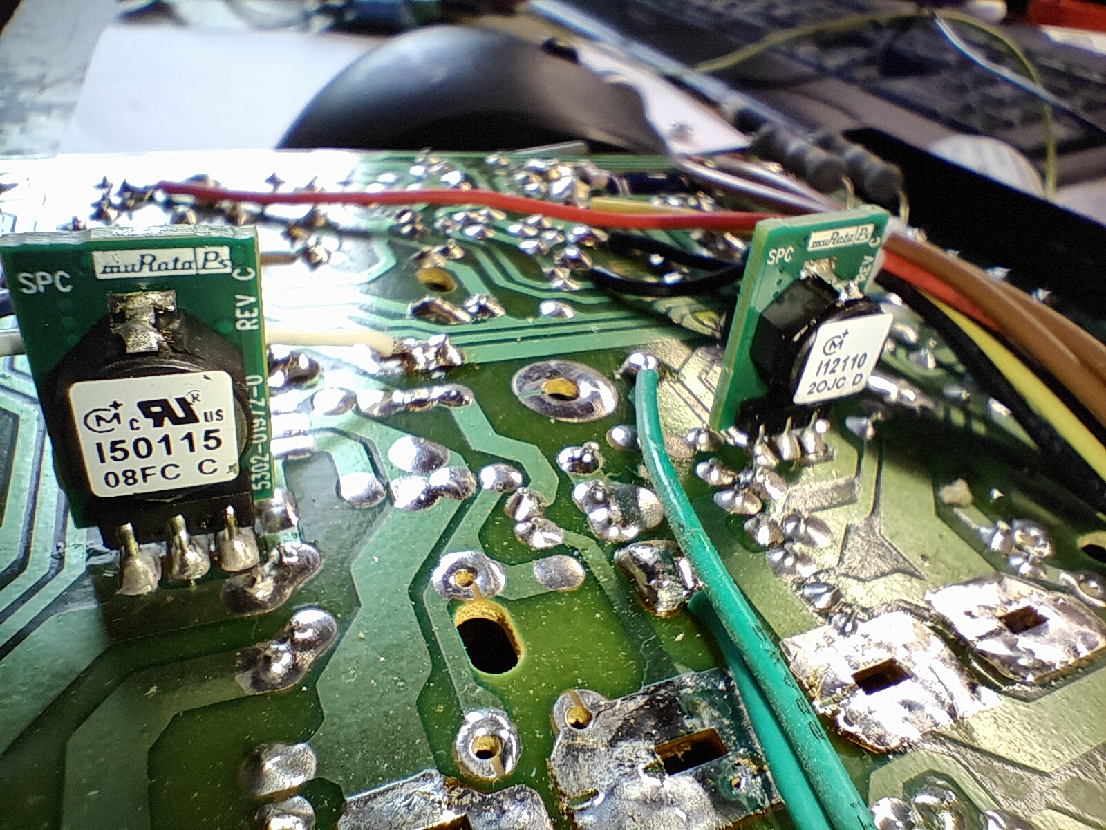
Kadangi gedimas kaip ir sutvarkytas, galima būtų truputį patobulinti maitinimo šaltinį. Visų pirma tie linijiniai baisuokliai LM7805 ir LM7812, 5V ir 12V gamybai – metam juos lauk ir dedam gerus impulsinius DC/DC konverterius.
Taigi, turim žymiai efektyvesnį ir netgi truputį galingesnį daikčiuką. Tas pat bus ir su 12V dalimi.
Štai jau abu stabilizatoriai impulsiniai:
Ir kai jau viskas surinkta, padarykime trumpą testuką.
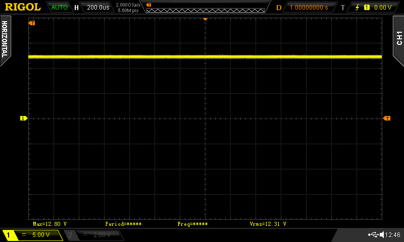
12VDC impulsinio stabilizatoriaus išėjimo oscilograma ir atfiltruota AC dedamoji, be apkrovos. matome, kad bendrai 12V įtampa išlaikoma gal gerai, tačiau visgi yra apie 100 mVp-p pulsacija.
5VDC impulsinio stabilizatoriaus išėjimo oscilograma ir atfiltruota AC dedamoji, be apkrovos. matome, kad bendrai 12V įtampa išlaikoma gal gerai, tačiau visgi yra apie 40 mVp-p pulsacija su 120 mVp-p „spygliais”. Tokie dalykai galėtų būti pataisyti papildomais išėjimo kondensatoriais (keramika !), bet kadangi ir taip jie, iš principo, nėra labai jau blogi, tai paliekame taip, plius maitinamuose prietaisuose beveik garantuotai bus maitinimo/filtruojantys ir t.t. kondensatoriai. Reikai nepamiršti, kad šitų impulsinių maitinimo šaltinių tikslumas ir efektyvumas prie mažų srovių (o mūsų atveju srovė 0A) yra prastas, užtai prie nominalios – superinis, net apie 90-95%, tai ir pulsacijos, ir visi kiti parametrai bus dar geresni, esant net ir šiokiai tokiai apkrovai, impulsiniai maitinimo šaltiniai dirbs geriau, pulsacijos bus mažesnės net ir be kondensatorių. O nauda naudojant impulsinius akivaizdi – dvigubai didesnis efektyvumas, mažesnis kaitimas, visokeriopos apsaugos ir t.t.
Pereikime prie pagrindinio maitinimo šaltinio dalies.
Nustačius panašiai 5VDC turime gerą stabilumą (be apkrovos), pulsacija tik apie 30 mVp-p.
Nustačius panašiai 12VDC irgi turime gerą stabilumą (be apkrovos), pulsacija irgi tik apie 30 mVp-p. Panašu, kad dirba linijiniame režime ir todėl man kaip ir norėtųsi sumontuoti papildomą aušinimą. Bet maksimaliais galingumais ir ilgą laiką maitinimo šaltinis nedirbs, tai paliekam taip, kaip numatyta gamintojo.
Pamiršau parašyti – kontaktinė kaladėlė irgi pakeista, bet negaliu parašyti jos modelio ar detalės kodo – nupirkau kitą tokį patį maitinimo šaltinį (labai pigiai, nes neveikiantis) ir panaudojau jo kontaktinę kaladėlę.
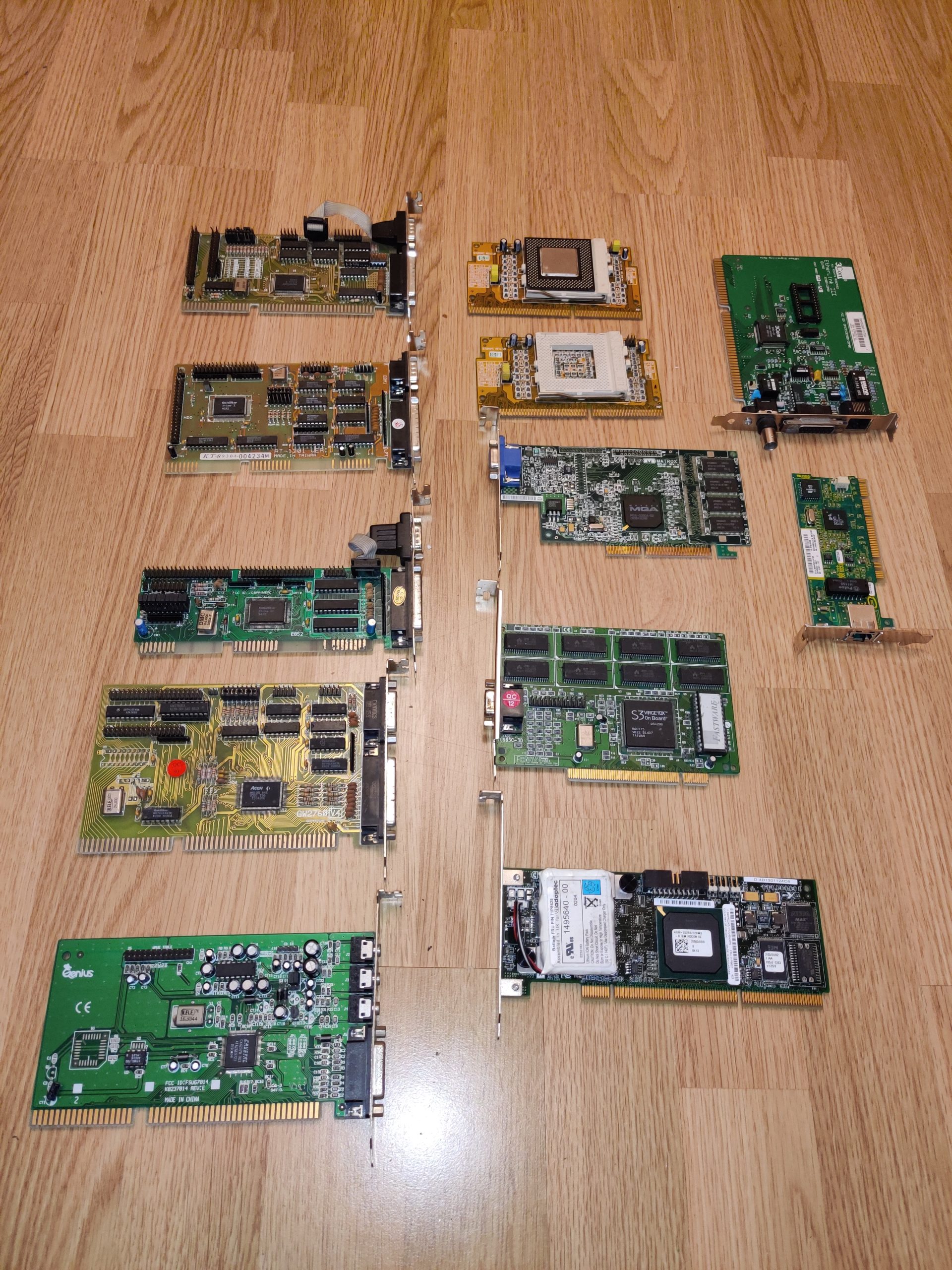
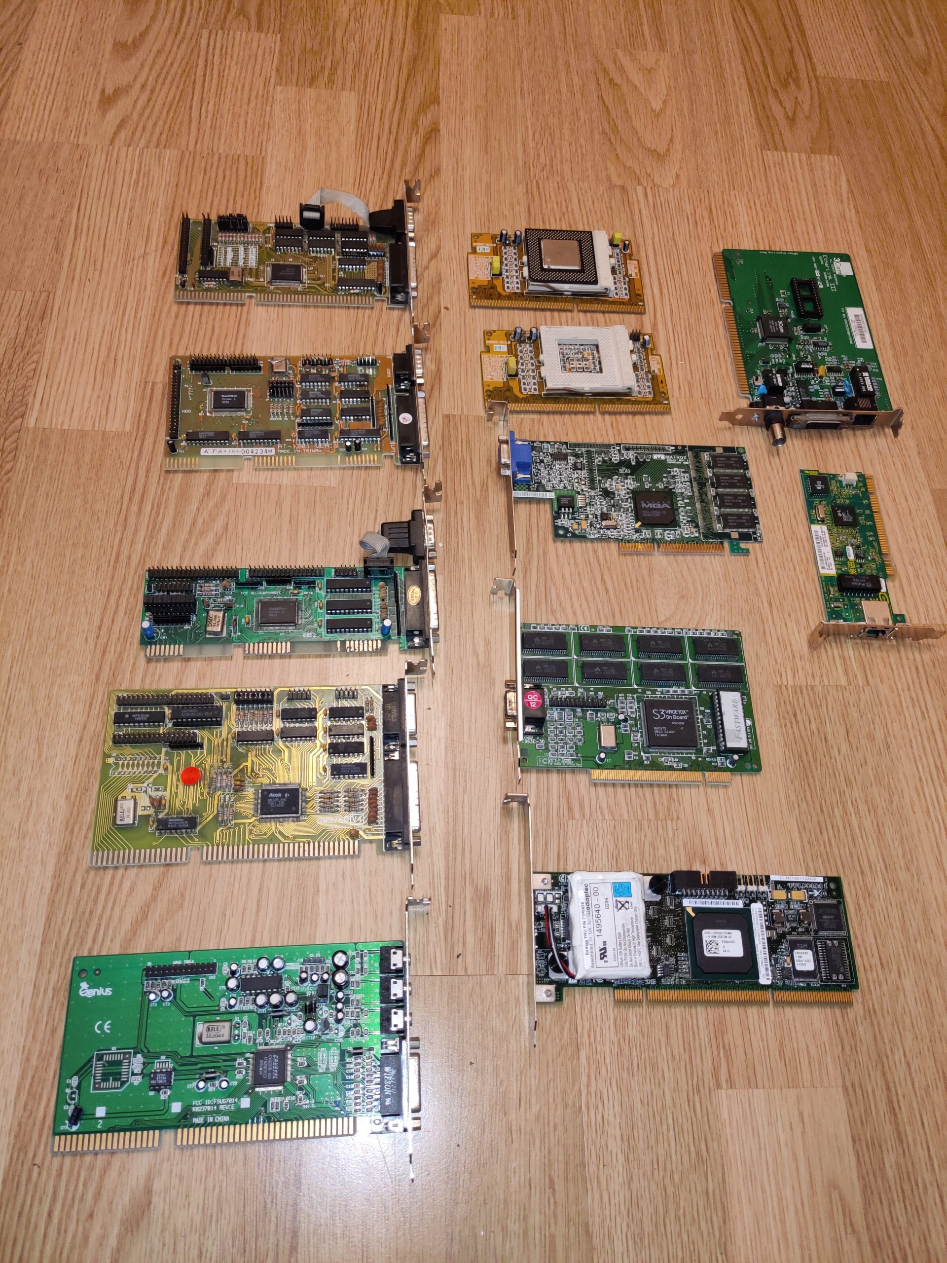
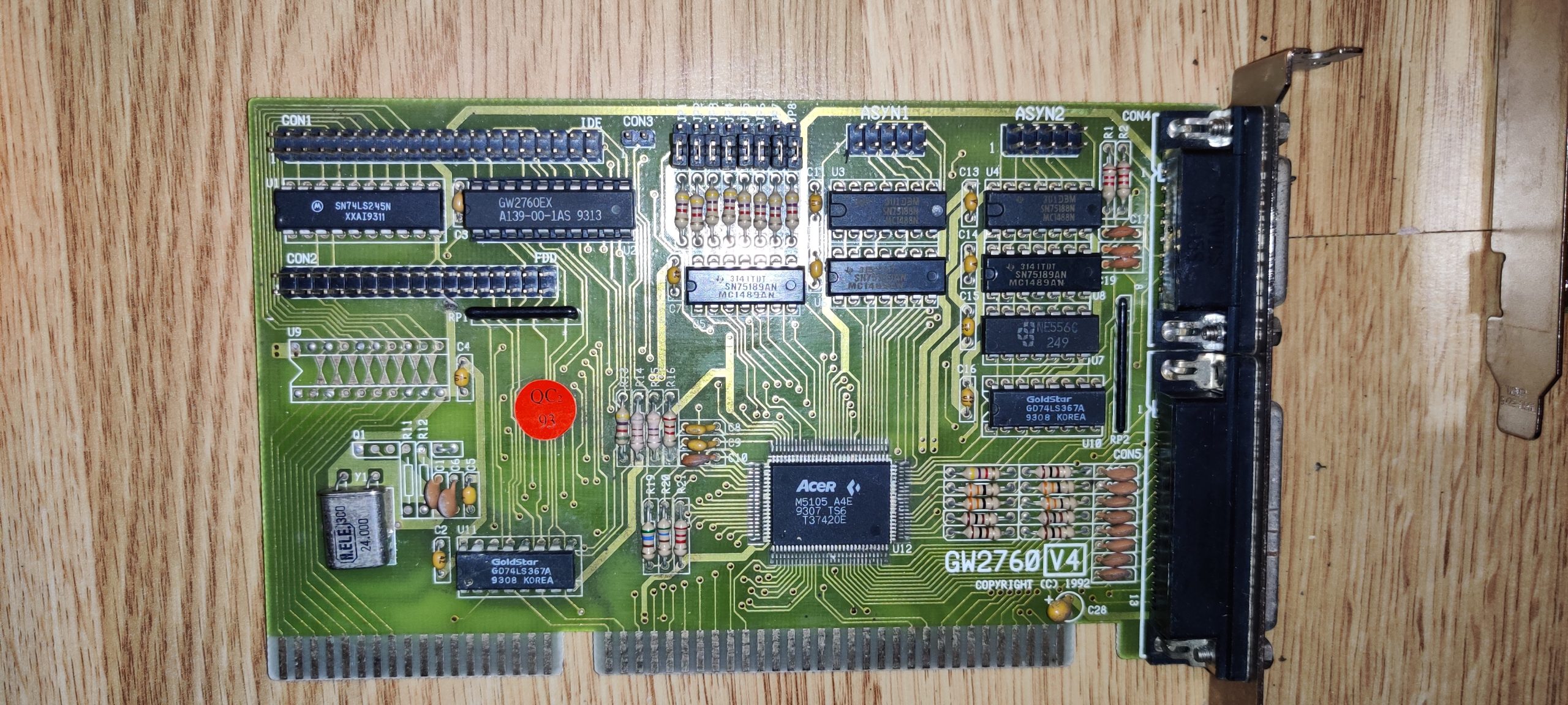
Sekanti daiktas iš kolekcijos – Acer GW2760 V4 super IO plokštė, skirta 16 bitų ISA prievadui, pagaminta 1993 metais.
Superinis HDD ir FDD kontroleris, su visais reikiamais interfeisais (COM1, COM2 arba RS-232, LPT, Game). jame sumontuotas labai geras lanksčiųjų diskelių diskasukio valdiklis (FDC – Floppy Drive Controller) Acer M5105 A4E, galintis skaytiti ir rašyti praktiškai bet kokio formato diskelius (taip taip, vienpusius/single density irgi). Turėtų sugebėti dirbti su:
Dviem 360 KB diskasukiais
Dviem 720 KB diskasukiais
Dviem 1,2 MB diskasukiais
Dviem 1,44 MB diskasukiais
Ir turėtų sugebėti dirbti su bet kuriais dviem diskasukiais iš sąrašo, nebūtinai vienodais.
U9 – matomi tik trumpikliai tarp ISA ir IDE jungčių. Kadangi takeliai eina į IDE duomenų linijas, manyčiau, kad esant poreikiui, galima pjauti trumpiklius ir dėti papildomą SN74LS245N buferį atitinkamoms duomenų linijoms. Keista, kad mikroschemos maitinimo kondensatorius C4 yra.
U10, U11 – GD74LS367A – GoldStar gamybos buferis, kurio aprašymo rasti nepavyko, todėl aprašymas Texas Instruments analogo.
U12 – M5105 A4E – valdiklis, bet vat normalaus aprašymo rasti taip ir nepavyko.
Jungtys:
CON 1 – 40 kontaktų IDE jungtis
CON 2 – 34 kontaktų FDD jungtis
CON 3 – Spėju, jungtis LED, HDD/FDD aktyvumo indikacijai
CON 4 – žaidimų prievadas (Game port)
CON 5 – LPT jungtis
ASYN 1, ASYN 2 – COM/RS-232 juntys
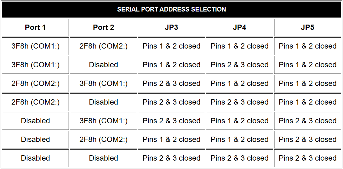
Lyg ir viskas. O kas per gauja trumpiklių JP1-JP8? Įprastai jais nustatomos funkcijos, pertraukimų adresai, LPT/COM nustatymai. Neilgai paieškojus radau ir nustatymus (šitam variantui gali būti ne tokie ):
Kadangi tas GW2760 buvo gaminamas keleto gamintojų, štai dar vienas variantas, GW2760PX:
Draiveriai… Daraiverių kaip ir neturėtų reikėti, nes viską turėtų padaryti BIOSas, o konfigūracija trumpikliais…
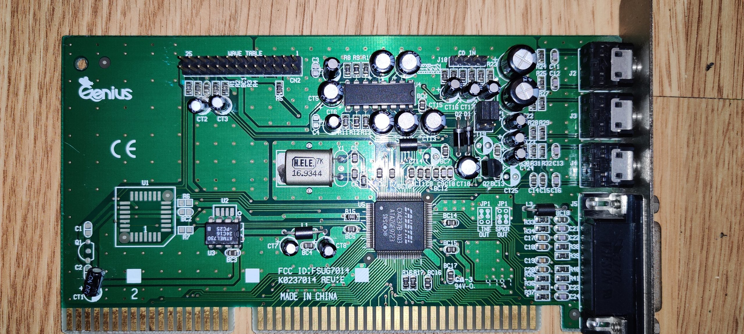
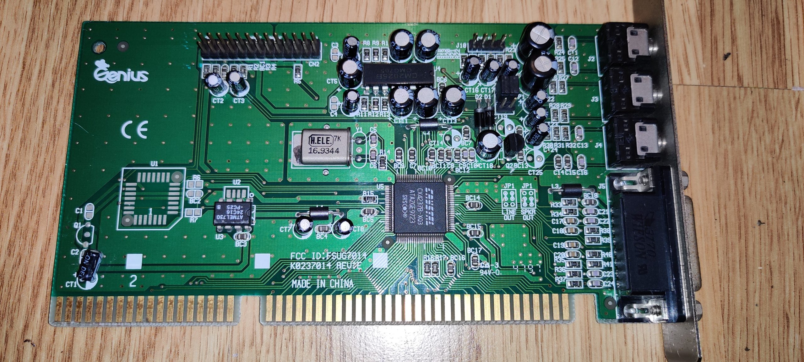
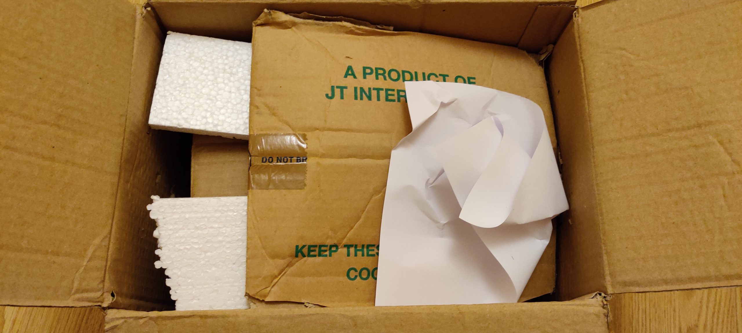
Taigi, pirmasis eksponatas iš gautos dėžės – Genius K0237014 Rev. E garso korta. Tai 16 bitų garso korta, skirta ISA jungčiai, iš, panašiai, 2005-2009 metų periodo.
Turi jungtis GAMEPORT/MIDI, mikrofonui, linijiniam įėjimui ir audio išėjimui. Audio išėjimas konfigūruojamas trumpikliais, gali būti linijinis arba garsiakalbiams (t. y. į stiprintuvą arba į garsiakalbius/ausines). Valdiklis Crystal CX4237B-XQ3, šalia dar Atmel 26C16 EEPROMas, kiek aukščiau – CM2025B stereo stiprintuvas. Viršuje keturių kontaktų CD Audio jungtis ir didelė jungtis papildomam „Wave Table” blokui. Tas blokas tai papildoma ROM atmintis, kurioje saugomi instrumentų garsai, o prireikus pagroti, kompiuteris juos suklijuoja į reikiamą audio signalą, taip gaunant žymiai gražesnį, autentiškiau skambantį instrumentų garsą. Aišku programos, pavyzdžiui, žaidimai, turėtų mokėti naudotis papildomomis galimybėmis, o ne tik vien PCM skaitmeniniu garso generavimu. Žaidimuose, kurie tą sugeba, garso efektai būtų pasirekami kaip ir buvo – tarkim „Sound Blaster”, o muzika būtų pasirekama tarkim „General MIDI” arba „MT-32” (jeigu Roland gamybos priedas). Reiktų pabandyti nusipirkti kokį nors šiuolaikinį priedėliuką, pajungimui į „Wave Table” jungtį.
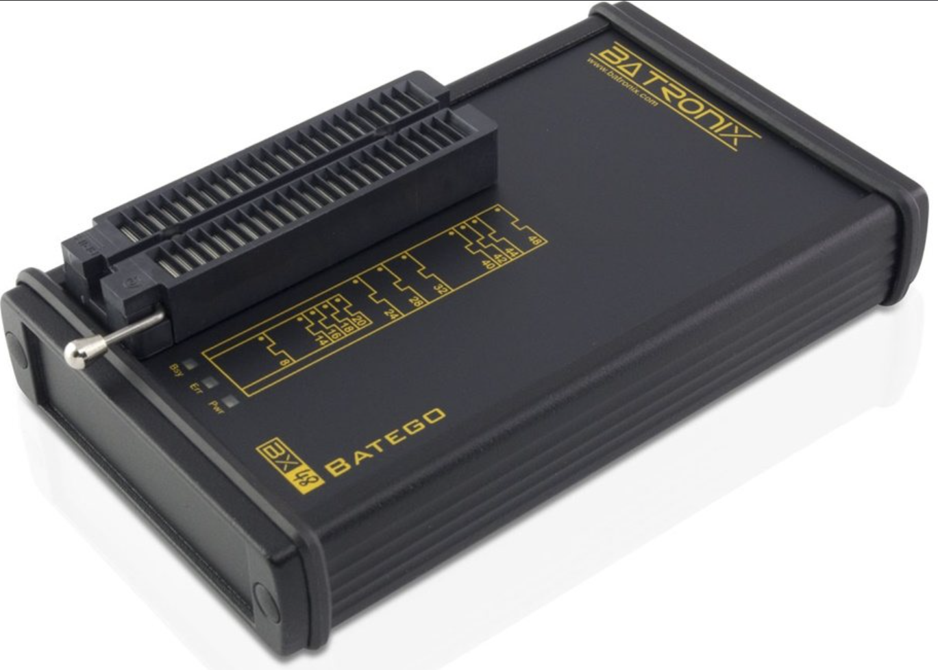
Šito reikalo istorija tęsiasi jau kokia 15 metų, tai pradėsiu iš toli. Kažkada, dar universiteto laikais, prisireikė programatoriaus, tuomet ant bangos buvo Willem’as, tuomet jį pasidaryti buvo galima sąlyginai nesunkiai, o svarbiausia gerokai pigiau nei pirkti gamyklinį programatorių. Dirbo per LPT (DB25) prievadą, reikėjo konfigūruoti trumpikliais ir buvo lėtas, bet skaitė kažkuriuos EEPROMus, kurių kiti pigūs programatoriai „neįkąsdavo”, nors su tais EEPROMais dirbo dar lėčiau (o gal ten buvo EPROMai). O dabar irgi pilna jo klonų, AliExpress’e ir šiaip pas entuziastus. O aš kažkaip nenorėjau tokio, reikėjo gero, universalaus, dirbančio per USB prievadą ir tuomet pirkau AliExpress’e TOP2048 programatorių. Nors jo programa (TopWin 6) buvo stipriai Chinglish, bet jis buvo pigus (anuomet mokėjau gal 78 $) ir su labai dideliu palaikomų mikroschemų sąrašu. Ir puikiausiai juo naudojomės tikrai ilgą laiką, kol pagaliau įsirėmėme į Windows 10 ir faktą, kad TopWin programa nu niekaip nesusibendravo su Windows 10 ir programatoriaus draiveriu. Po to kurį laiką dar bandė tas programatorius dirbti Windows XP aplinkoje, bet sukosi virtualkėje, bet dabar, atsinaujinus laboratorijos kompiuterį, sugalvojau, kad reikia atsinaujinti ir programatorių. Ufff, va tokia va tatai istorija, kodėl čia viskas atsitiko. Taigi, išstudijavęs rinkoje esančius programatorius, palyginęs jų galimybes, savo poreikius ir finansinius pajėgumus pasirinkau Batronix BX48 Batego II universalų programatorių. Jis atitiko visus pagrindinius pasirinkimo kriterijus:
Gaminamas Europoje
Geras palaikymas, pageidautina Europoje
USB jungtis
Dirbantis su Windows 10 ir Windows 11
Didelis palaikomų mikroschemų sąrašas
Patogi programa
Taigi, Batronix – Vokiečių įmonė, reikia tikėtis vis dar išlaikiusi ta vokišką kokybę. Palaikymas – kurį laiką bendravau, patiko, ypač tai, kad pasakė – „jeigu kokios mikroschemos nėra sąraše, pridėsime pagal pageidavimą ir greičiausiai nemokamai”. USB juntis yra, ką tik instaliavau ir išbandžiau Windows 11 operacinėje – veikia, programa tikrai funkcionali, tai kol kas visko net neišbandžiau, bet kiek bandžiau patiko. Ne viskas joje ten gal patogu, kai kada atrodo, kad net per daug funkcijų, bet tas žymiai mažiau trukdo, nei funkcijų trūkumas. O kad jau turim gamintoją, tai štai ir jų gaminamų programatorių palyginimas:
Kadangi programatorių perku tikrai ne vieniems metams ir negali žinoti, kokias mikroschemas gali tekti programuoti ateityje – pasirinkau patį pačiausią, BX48 Batego II už 579,59 € (tiesa gavau nedidelę nuolaidėlę ir nemokamą siuntimą).
Forma patiko, juodas, mažiukas, su trim LEDukais ir didele ZIF jungtimi mikroschemoms. Dabar beliko tik užsipirkti reikiamų adapterių, kol kas tik PLCC-44. Palaikomų mikroschemų sąrašas yra čia. Svarbiausia, kad palaiko ir visokius senus ir jau ekskliuzyvinius čipus :).
Prieš kurį laiką įsigijau ir ST Link V2 programatorių, originalas, gražioje dėžutėje. Aprašymas iš ST puslapio:
The ST-LINK/V2 is an in-circuit debugger and programmer for the STM8 and STM32 microcontrollers. The single-wire interface module (SWIM) and JTAG/serial wire debugging (SWD) interfaces are used to communicate with any STM8 or STM32 microcontroller located on an application board. In addition to providing the same functionalities as the ST-LINK/V2, the ST-LINK/V2-ISOL features digital isolation between the PC and the target application board. It also withstands voltages of up to 1000 Vrms.
STM8 applications use the USB full-speed interface to communicate with the ST Visual Develop (STVD-STM8) or ST Visual Programmer (STVP-STM8) software, or with integrated development environments from third-parties.
STM32 applications use the USB full-speed interface to communicate with the STM32CubeIDE software tool or with integrated development environments from third-parties.
Pas mane tas paprastesnis, be izoliavimo. Skirtas STM8 ir STM32 valdikliams programuoti/debuginti.
Prisireikė man čia vienam projektukui stabilizuoti maitinimą, kad išsikraunant baterijai (9 V) įtampa būtų stabili (6-7 V). Vienas paprasčiausių būtų tą padaryti būtų DC-DC keitiklio naudojimas ir jau galvojau dėti jau pamėgtus Mornsun moduliukus, šiuo atveju K7812JT-500R3-LB (6,5 V 500 mA):
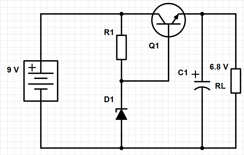
Kainuoja centus, efektyvus, stabilus ir geras. Bet kaip visada, lengviausi sprendimai ne man , todėl prisiminiau tokį senovišką žodį stabilitronas. Dabar tas daiktas vadinamas Zenerio diodu. Nebus jis toks jau stabilus temperatūriškai, bet šiuo atveju tiks, nes reikia pasikartoti skaičiavimo teoriją. Tipinė schema tokia:
Tranzistorius gali būti priešingo poliarumo, tada schema truputį kitokia. Bet schemoje visi tranzistoriai NPN tai tokį naudosiu ir stabilizavimui.
Teorija tokia – šitoks įtampos reguliatorius, sudarytas iš bipoliarinio tranzistoriaus, pajungto pagal emiterinio kartotuvo schemą, kurį valdo įtampos daliklis iš rezistoriaus ir stabilitrono. Daliklio išėjimas valdo tranzistoriaus bazę, taip valdydamas įtampą išėjime. Principe užtektų vien tik stabilitrono, bet su tranzistoriumi gaunama žymiai didesnė srovė išėjime. Svarbūs tranzistoriaus parametrai – maksimali srovė ir hFE. Susižymime sroves ir jų kryptis:
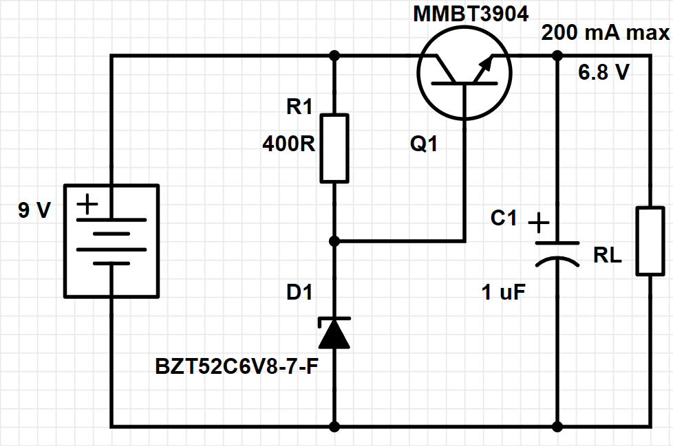
Schemoje naudojami MMBT3904 tranzisotriai, 40 V, 200 mA, hFE nuo 30 iki 300, priklausomai nuo kolektoriaus srovės.
Pagal kolektoriaus srovę manyčiau, kad hFE bus apie 200, todėl tokį skaičių ir naudosiu. Taigi, turime, kad hFE = 200, maksimali srovė 100 mA (realiai ten kokia 10 mA tereiks), skaičiuojame:
\[h_{FE} = {I_{OUT} \over I_B}\]
Iš čia:
\[I_B = {I_{OUT} \over h_{FE}}\]
\[I_B = {0,1_A \over 200}=0,0005_A\]
Toliau prisiminkime mūsų geriausio draugo Kirchhofo taisykles. Pagal jas, srovė per R1 bus lygi srovės per D1 ir bazės srovės sumai.
Naudojame 6,8 V stabilitroną, o maitinimas bus nuo 9 V baterijos (Krona arba 6LR61), tai ant rezistoriaus R1 turime nusodinti 9 – 6,8 = 2,2 V. Kai jau turime srovė per rezistorių ir įtampą, dėdės Omo dėsnio pagalba skaičiuojame rezistoriaus varžą:
\[R_{R1} = {U_{R1} \over I_{R1}}\]
\[R_{R1} = {2,2_V \over 0,0055_A}=400 \Omega\]
Jeigu baterija jau pasėdusi ir įtampa pakris, tarkim, iki 8 V, tuomet 8 – 6,8 = 1,2 V ir:


 and other readers who knows English. Some readers remember, that we already tested the work of

 , step by step. First lets initialize the HEARBEAT, so the on board LED would blink, showing, that the microprocessor is alive. To the „main(void)”, which runs only once, after the microprocessor is started:
 . So now we have some of the static things, now we need to show temperature on display and it looks like this:
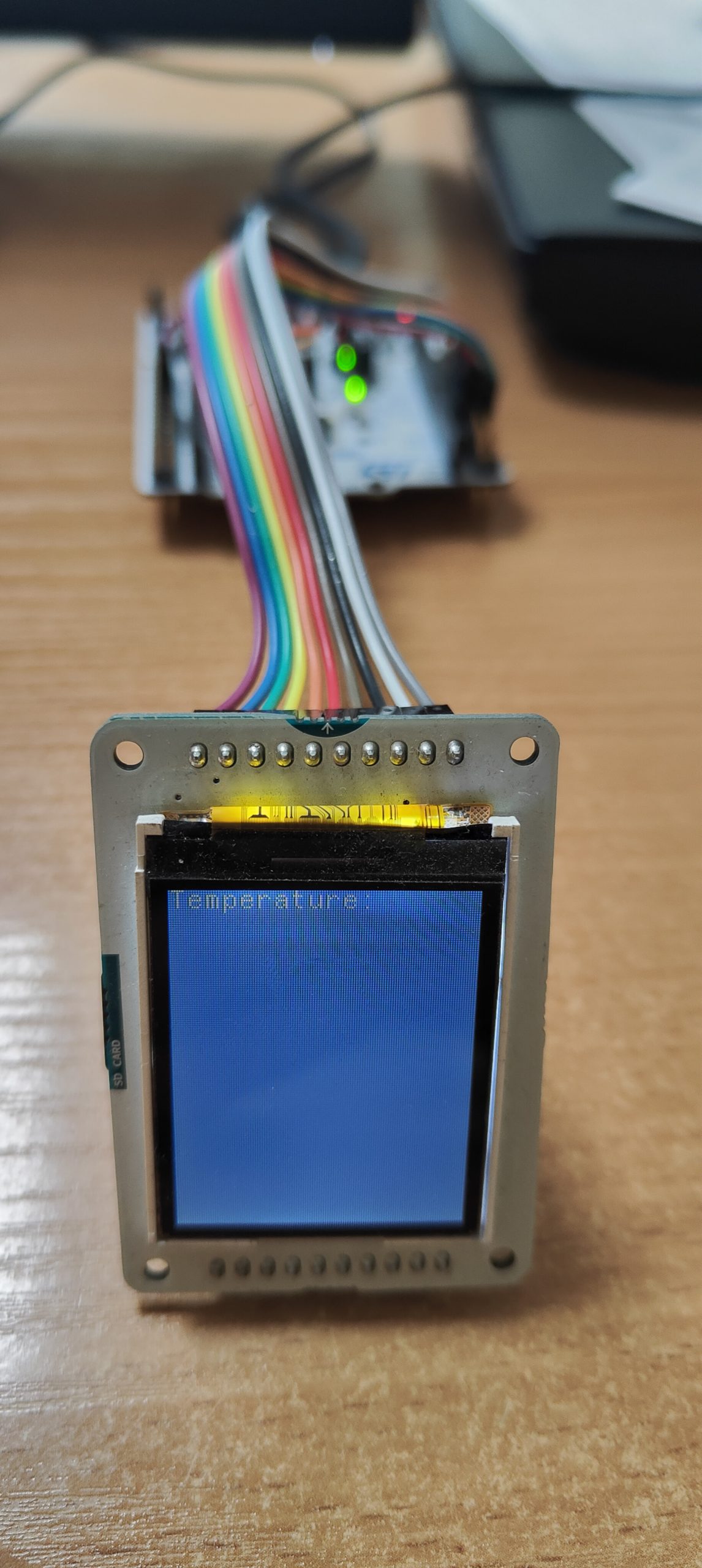


 . Lets toggle the HEATBEAT pin with our new delay function:
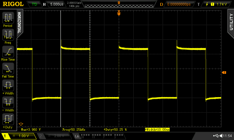


 .
.


 ):
):