The names of those power supplies are different, but inside they are all the same, with veeery slight differences. The brand names are Wanptek, Hanmatek, Naweisz, Sky TopPower, Circuitspecialists, Eventek and bunch of other brands and even without any brand, they all look pretty much the same and are priced at about 70-80 €.

The internals of the power supply are the same and looks like this:
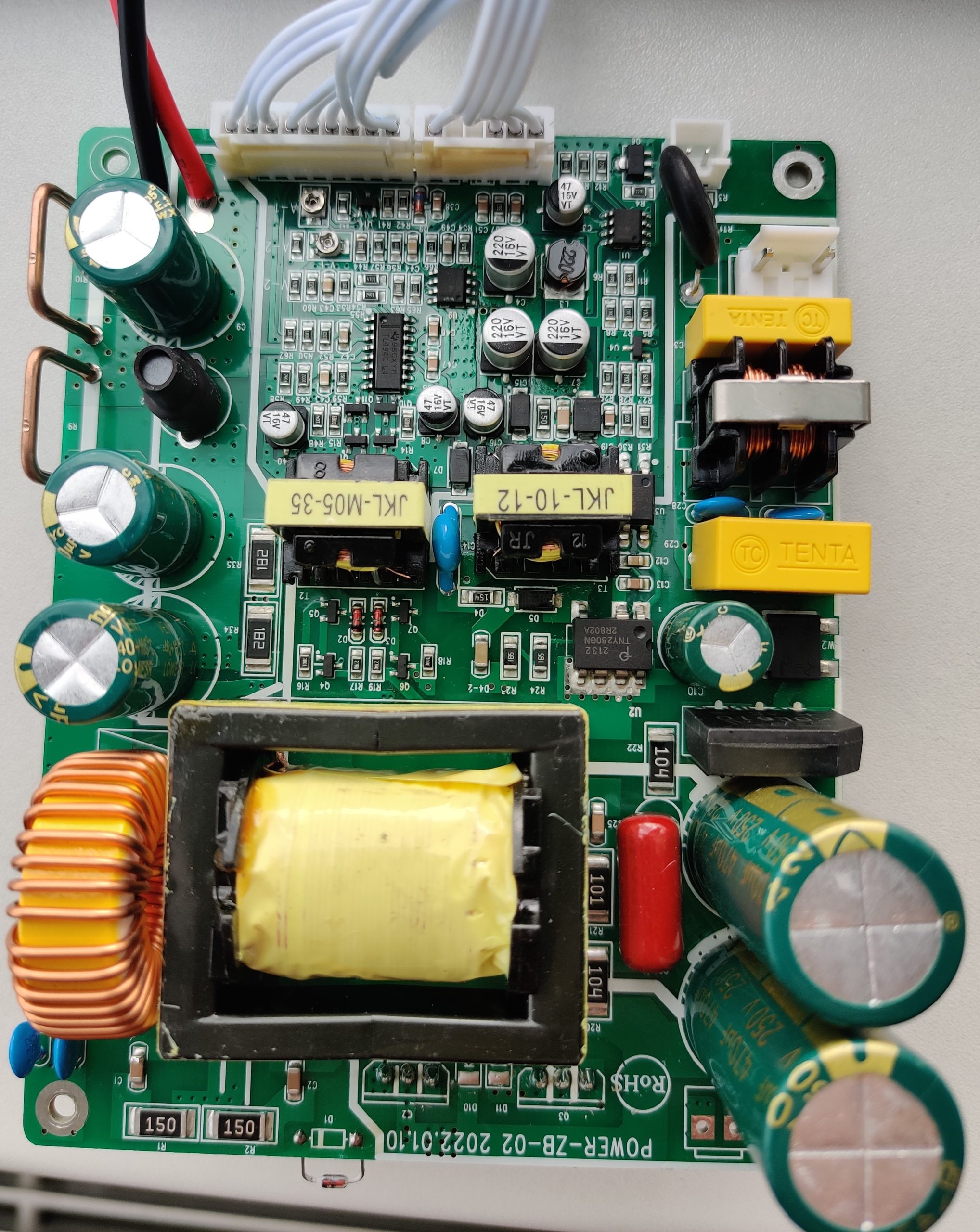
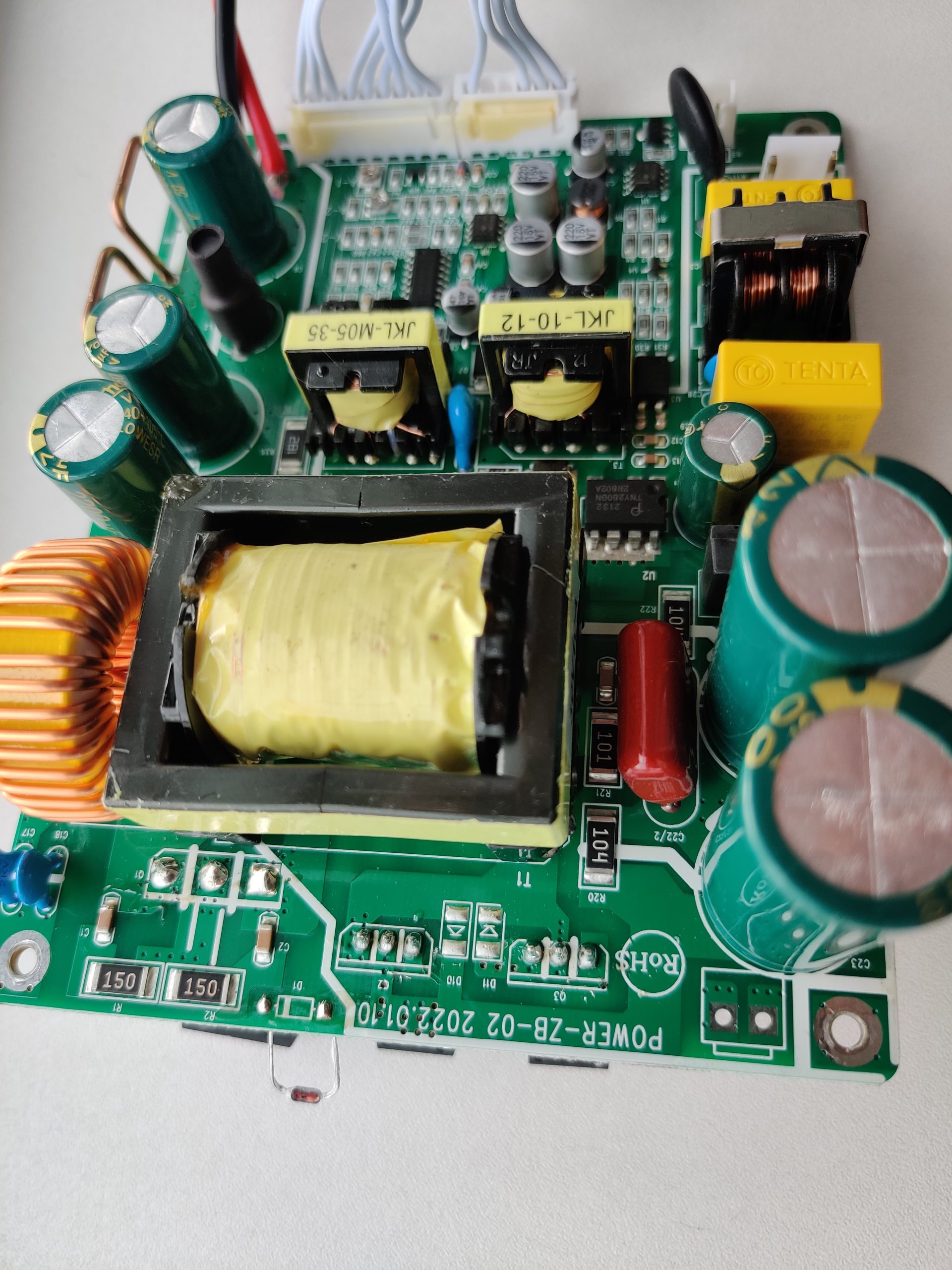
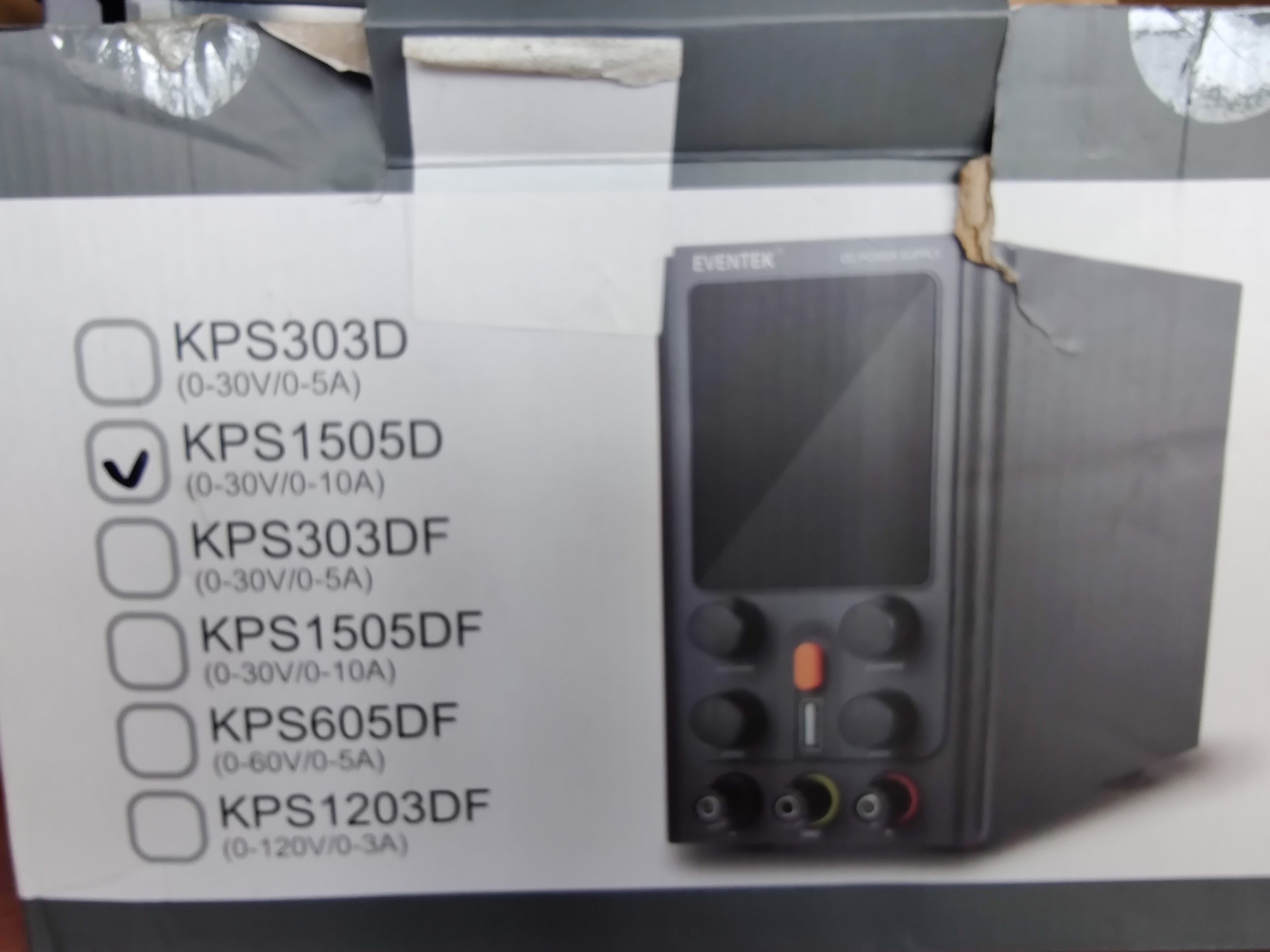
Pictures takes from the power supply I got for repair, exact model is KPS1505D, one of other models, sold by this „manufacturer”:
The power supply had burned main fuse (3A), so it was not long to find out that power transistors and diodes gave their souls to the god of electronics in form of smoke. And we all know – all electronics is made of smoke, when it goes out, electronics stops working. Well, before repairing, lets study this board for a while. By the way – as this power supply is so typical, I am not explaining about its functionality, controls and basic things like that.
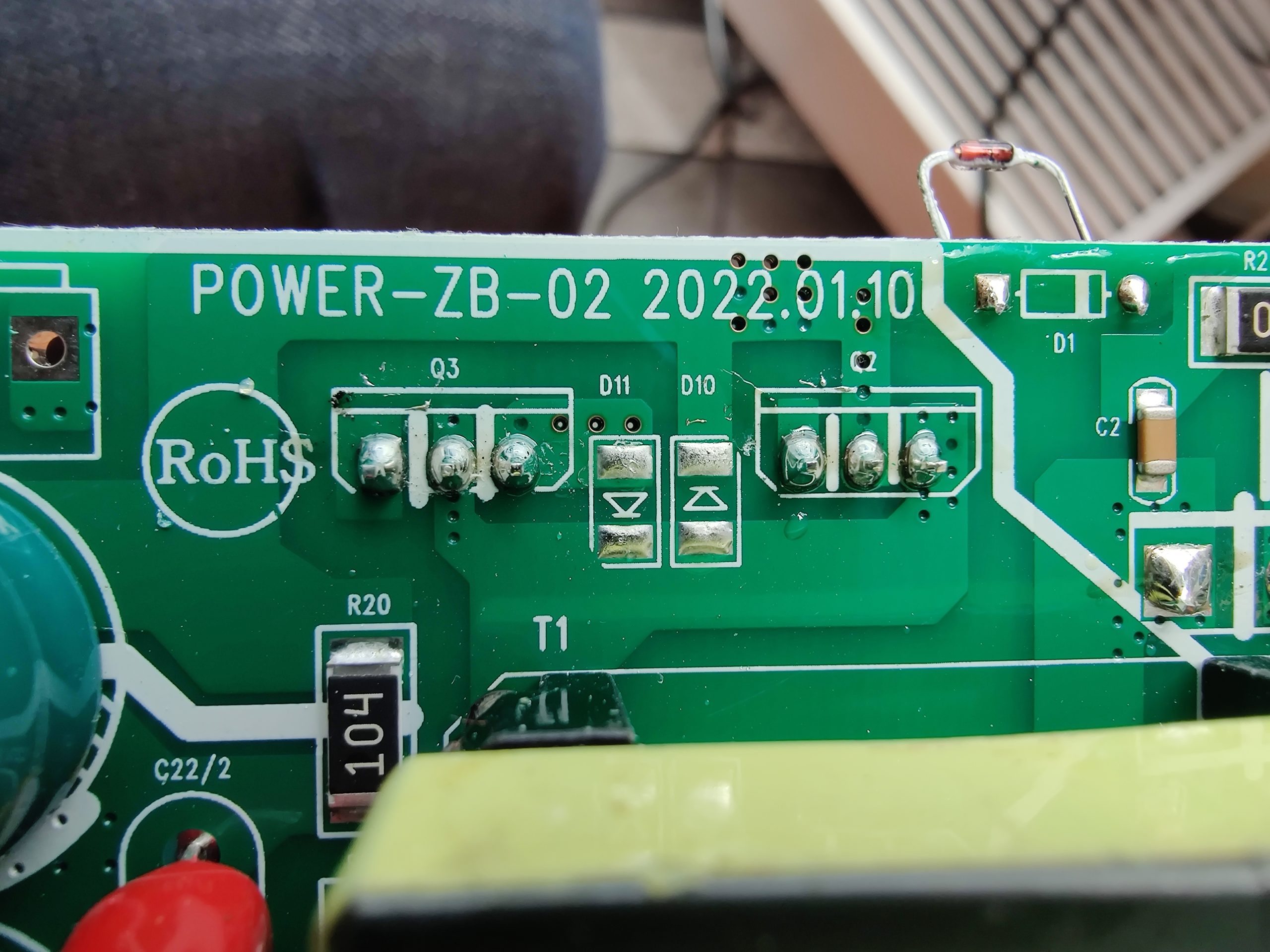
The main PCB is marked POWER-ZB-02 2022.01.10:
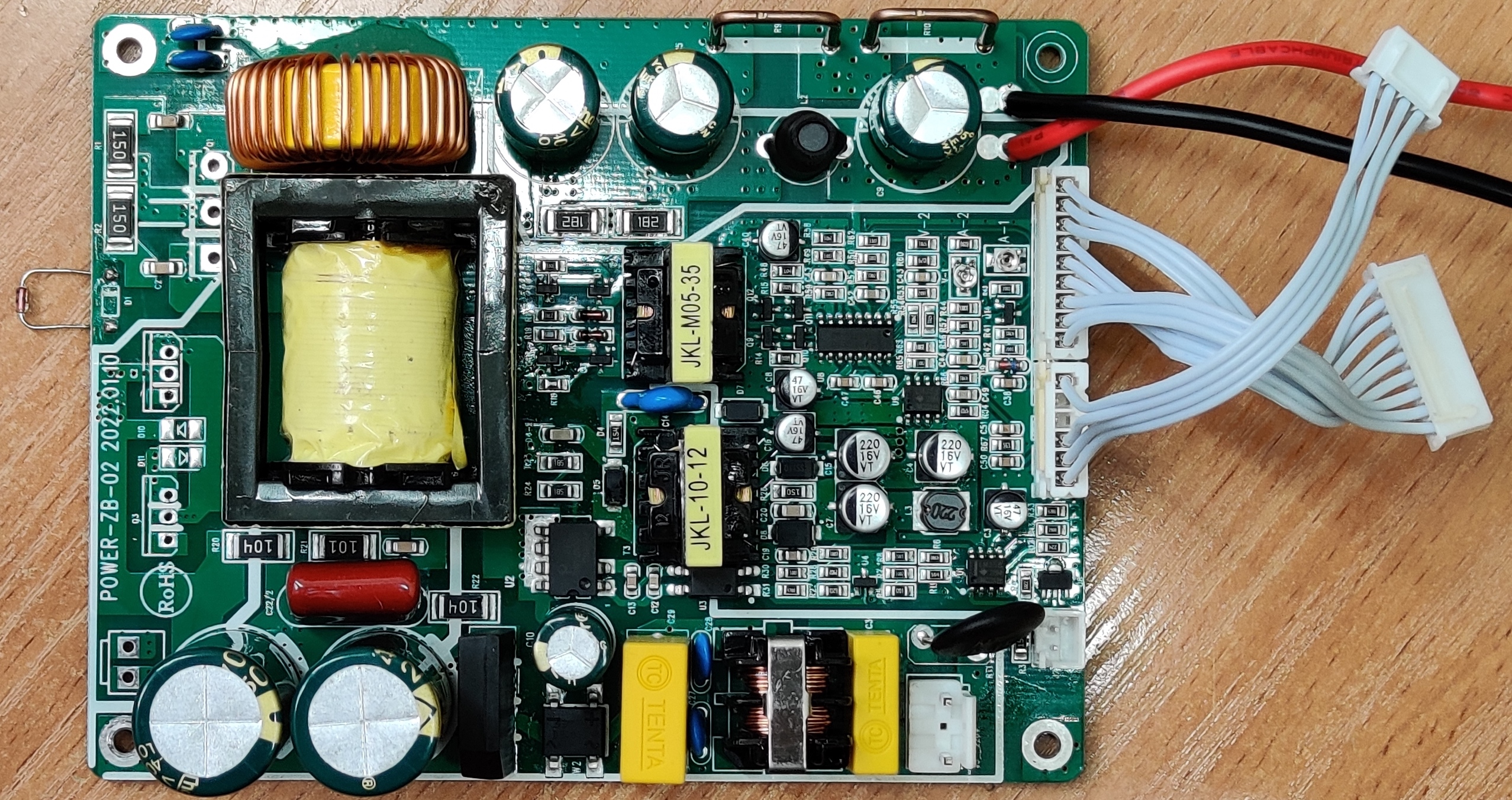
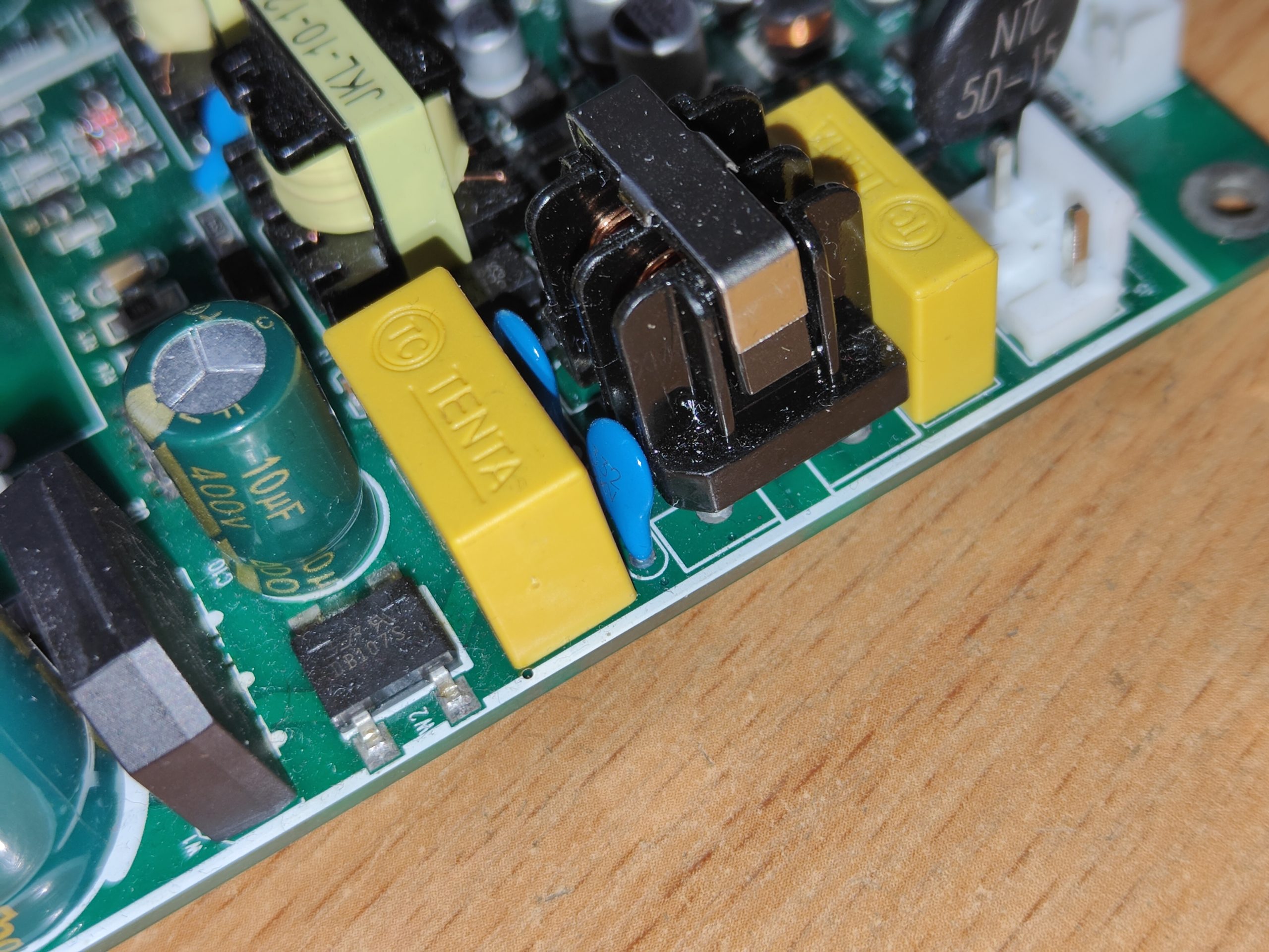
The white connector on the bottom right is for 230AC input and all this bottom part along the PCB is for input filtering, rectifying and stabilizing. So right to left – yellow input capacitor, common mode (CM) filter, which, with its ‘current compensated’ windings, provides high impedance to CM noise without saturation from line current, two small blue caps and one more yellow capacitor. Then a small diode bridge, yes, yes, the fuuuuuuull bridge rectifier (DB107S). This rectifier, together with the nearby electrolytic capacitor, that strange IC with 7 pins (TNY280GN) and JKL-10-12 transformer (skipping some minor SMDs) forms low power supply for logic and control ICs, LED indicators, etc.

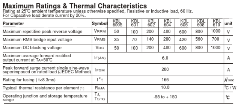
The bigger rectifier (KBL610) and two big electrolytes are for the power section of the device.
And on the left side of the PCB a place for missing connector, it wasn’t there, but on the other boards the main power selection switch (115VAC/230VAC) is connected. This version of device has no connector on the PCB and switch on the back panel, so, if you want to use it with low voltage power system just connect those two pins on PCB or put a switch – when pins shorted use 115VAC, when open use 230VAC. The rest of the board is, basically used to hold the main controller (TL494C). The TL494 or its clones or variants are used in all sorts and kings of PWM power supplies and, probably, in 95% of their population.
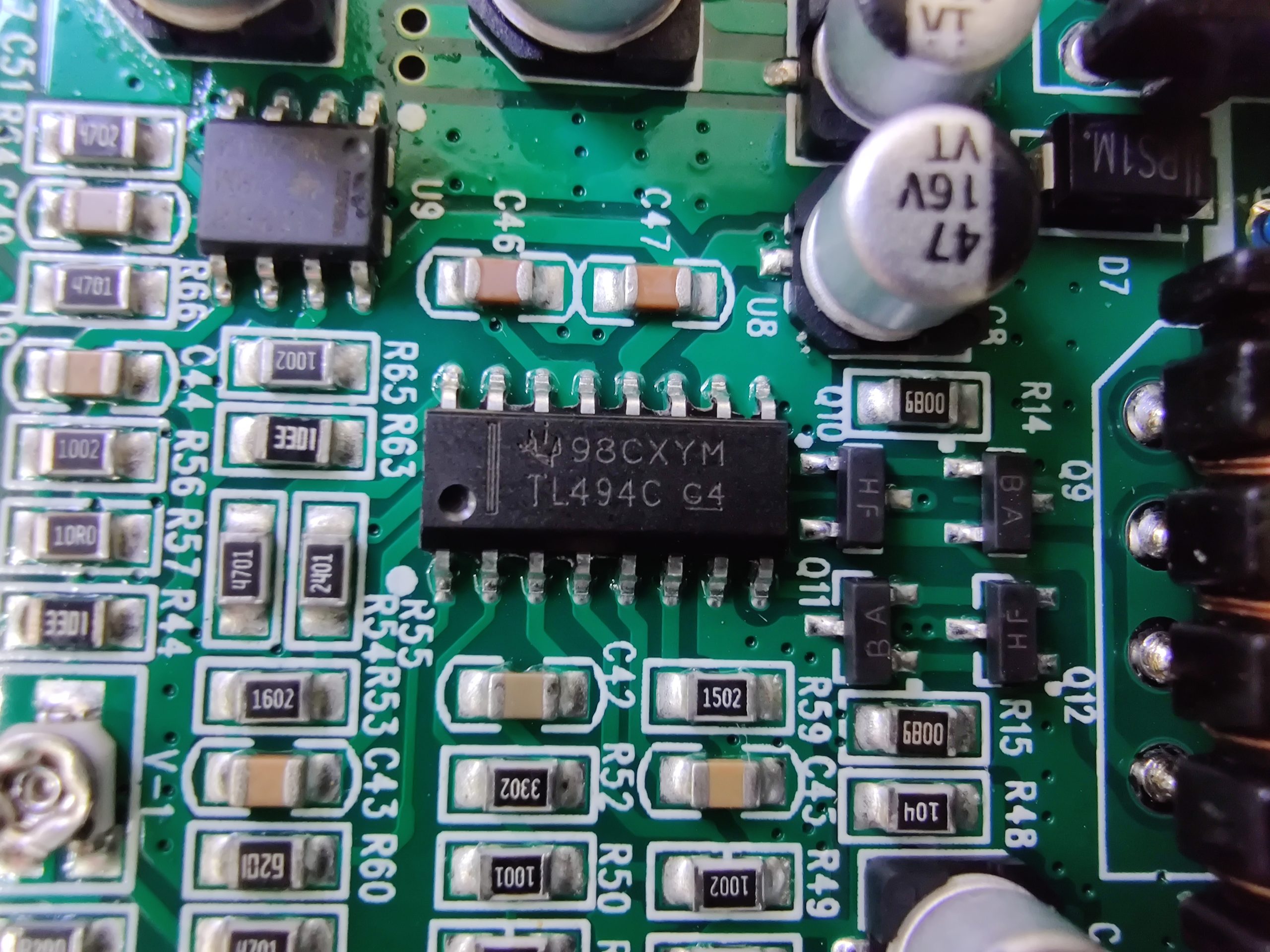
As this IC is so popular, there are plenty of schematics with it on the Internet, which would help you to make the repairs. I was surprised, but this version of board has all electrolytic capacitors marked as low ESR, which is good (hoping, that its not just marking  ). Even those big input filtering caps (470 µF 250V) are low ESR, which is not really needed for their job.

One of three output caps is also Changxin 2200 µF 35V Low ESR, other two Sanyo 1000 µF 50V, together with a big and small choke, they form the output filter (on the top of PCB picture). And thick copper wires on the negative trace are shunts for current measuring.
In the middle part of the PCB the main component is TL494, couple of op-amps, one of them turns on the fan when aluminum board with transistors and diodes get hot. The temperature is sensed by 1N4148 diode, drowned into thermal paste. The last things are power transistors and diodes:
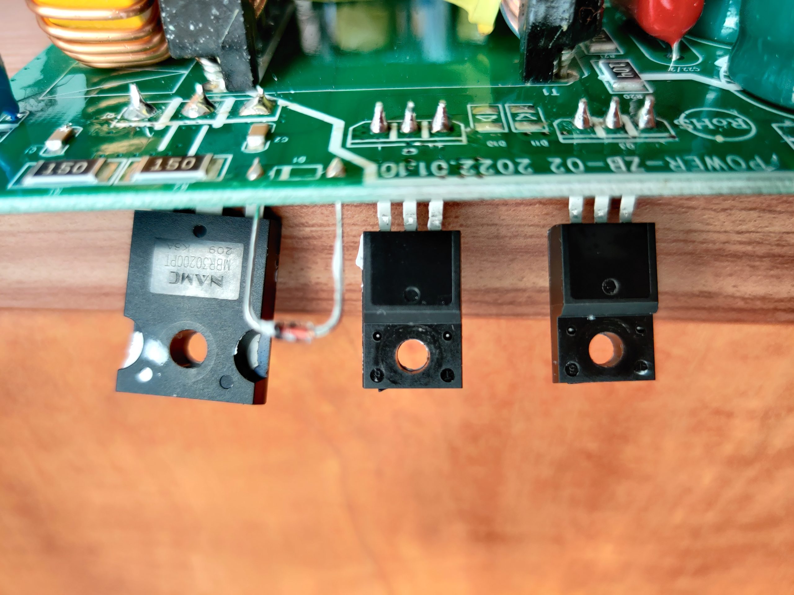

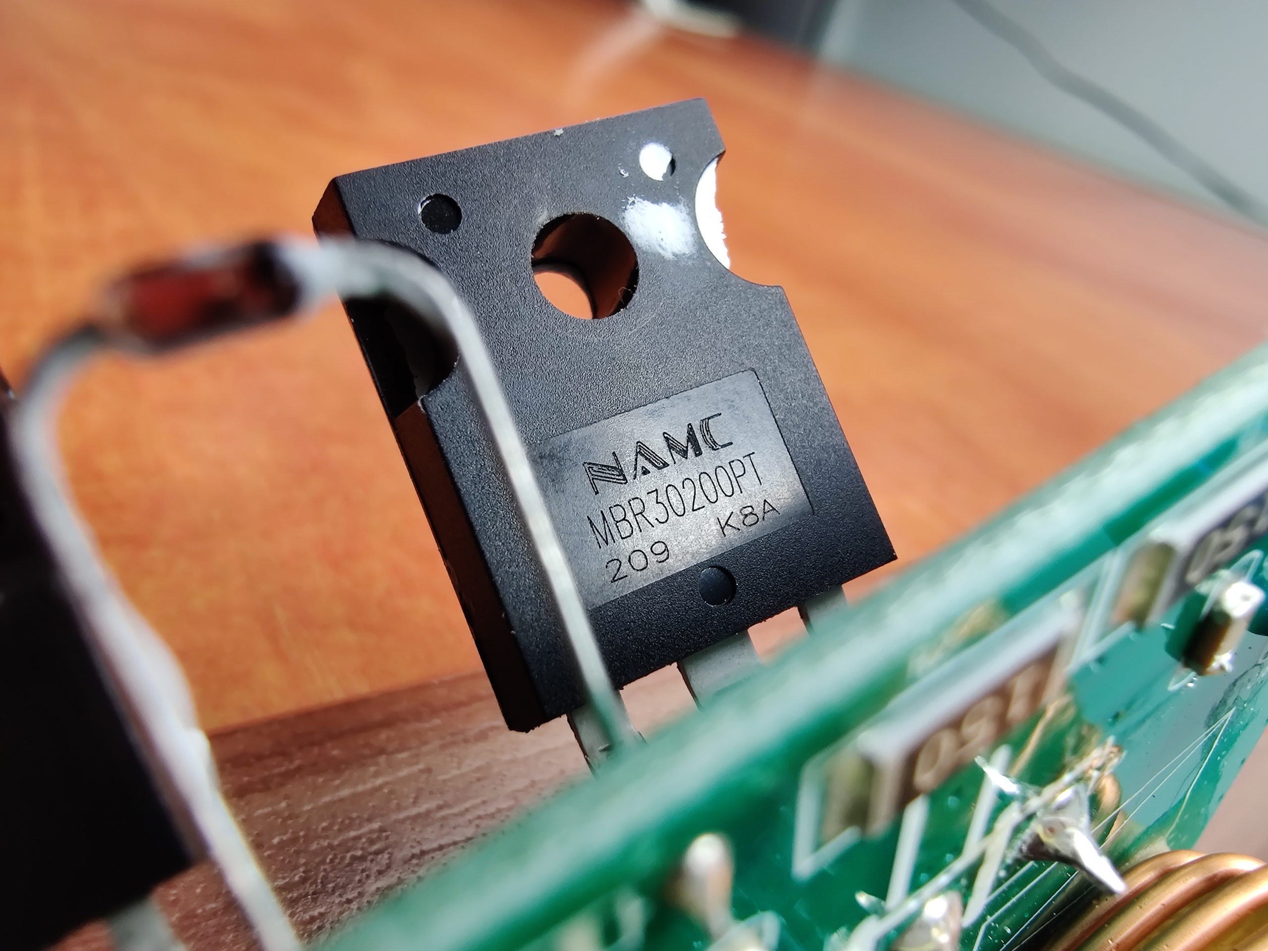
The big thing is a dual Schottky diode with common cathode – MBR30200PT. But the two transistors are blank, not marked  , guess what are they. Ok ok, I tell you, its 2SK3569.

And yes, it’s not recommended for new designs, most probably you wouldn’t find them for purchase eather. Unless fake AliExpress clones. Luckily, we have me and I already selected proper substitute – AOTF15S60L. Why particularly this one ? Because at the date and time of repair it suits all requirements:
- Analog or better than 2SK3569
- Cheap
- Available for purchase
This transistor a slightly better that original, is almost cheapest (~2,5€/piece) from the selection and is available for order – perfect :).
Parts received and soldered in, surprisingly nothing exploded, and power supply shows the set voltage. But the test under load was not successful – connected 0,62 Ω resistor and raised voltage to raise the current. At some point heard a clap and everything turned off. The current was not high, I think it was about 6-7 A, but can’t say for sure – I did not expected it to explode, so did not looked at the display all the time and also display refresh rate is not instant. Nevertheless, fuse blown, most probably transistors and diodes also. Let’s disassemble it again and see what happened. But it worked with some small current, liek couple of amps, so it might be, that TL494 is counterfeit and cannot work normally under bigger loads, while the idea of this power supply is to be fearless when speaking about currents up to 10 A or short circuit. Luckily, I still have some transistors and diodes left  .
.
To be continued after parts received and soldered in.
2023.10.12
Parts replaced and that did not helped, so we need to look deeper into the schematics. First of all desoldered the main transformer – the big yellow thingy, because its my first suspect (maybe the coil wires are damaged and shorts the transistors, so they pop and brings together the fuse). After desoldering tried the output part of the schematics for faults:
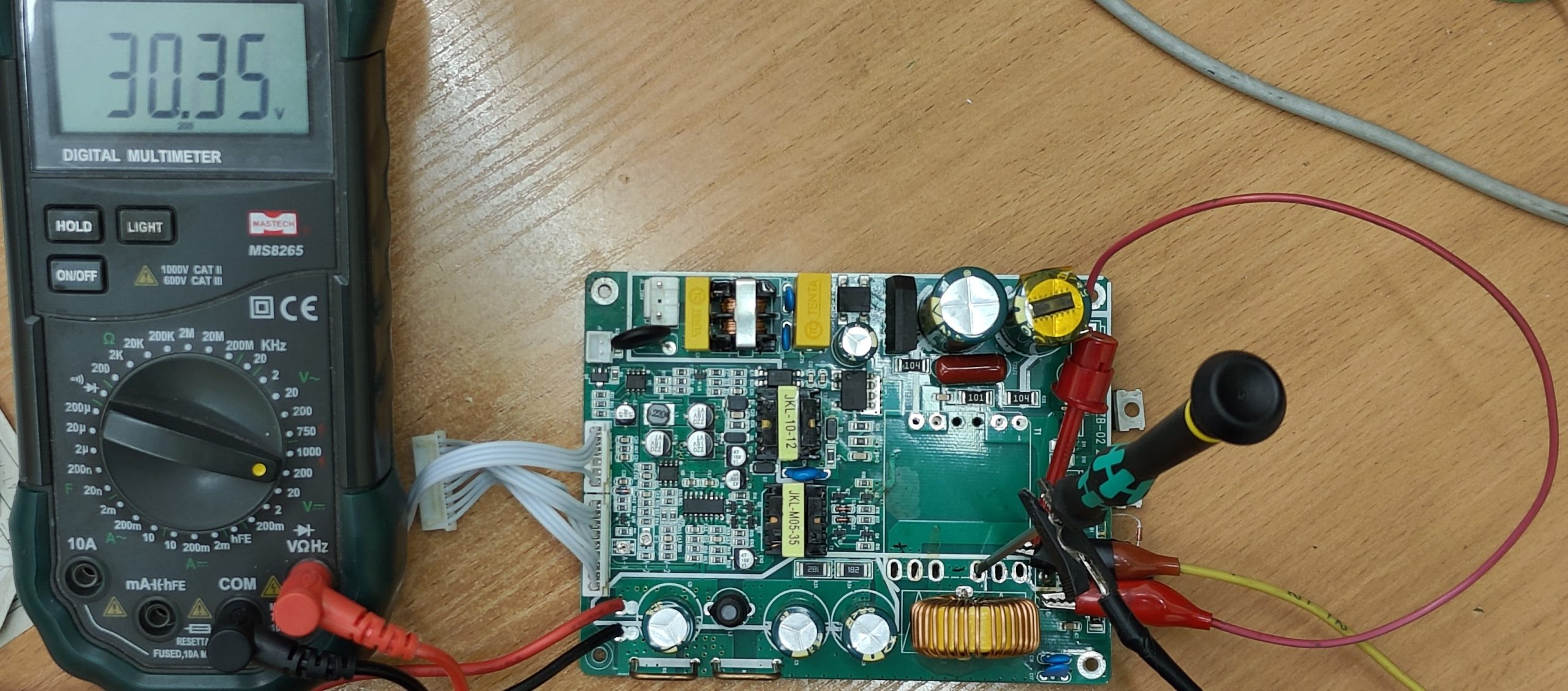
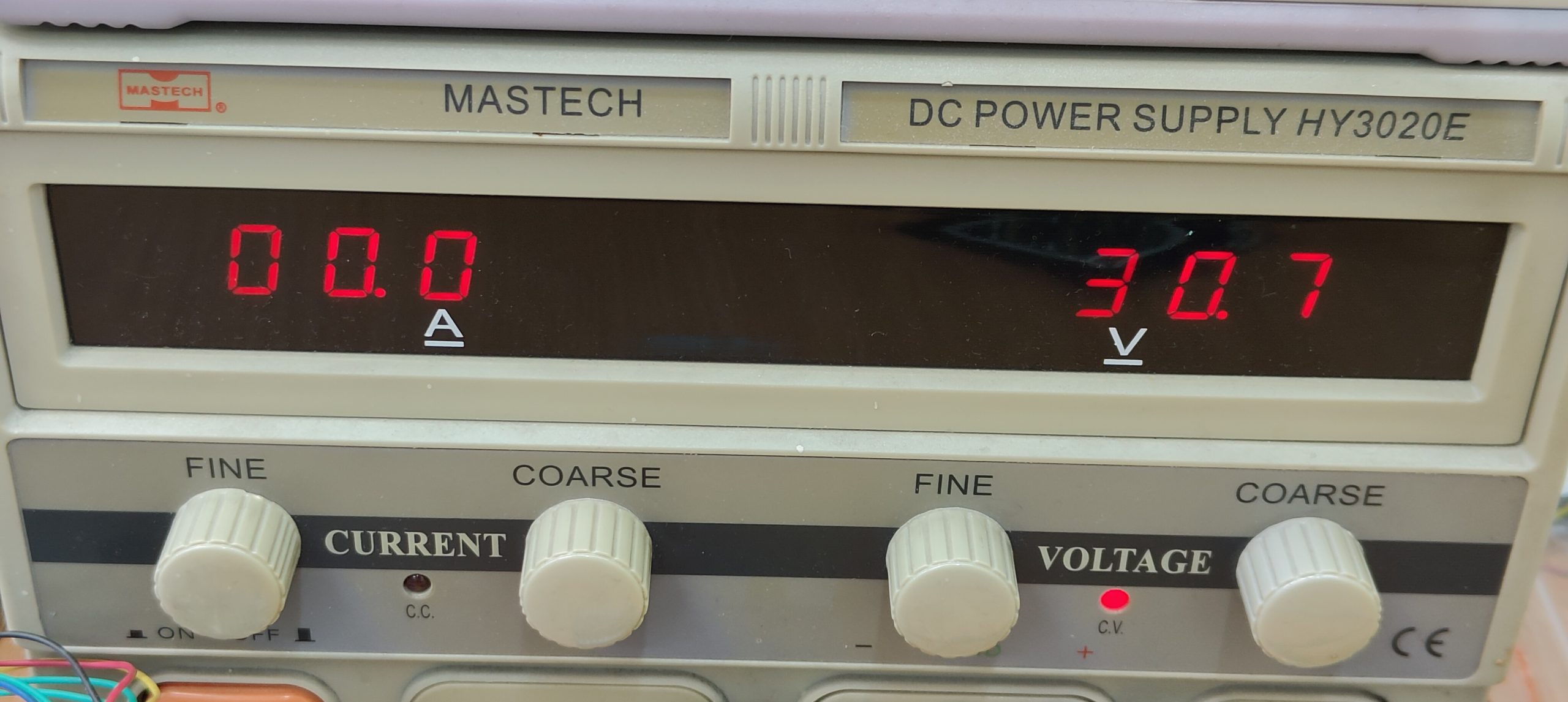
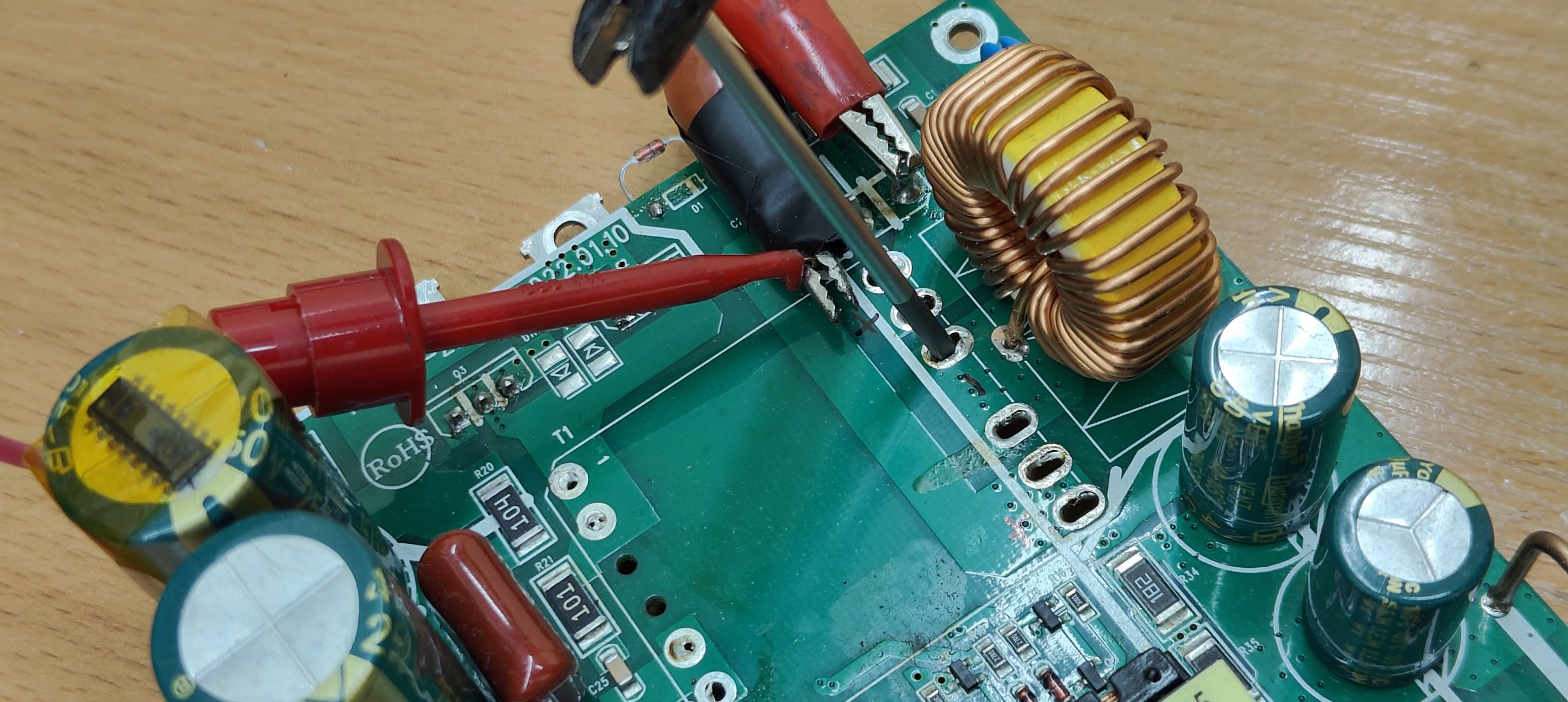
The idea is simple, but lets draw a small schematics, so it would be even more understandable.
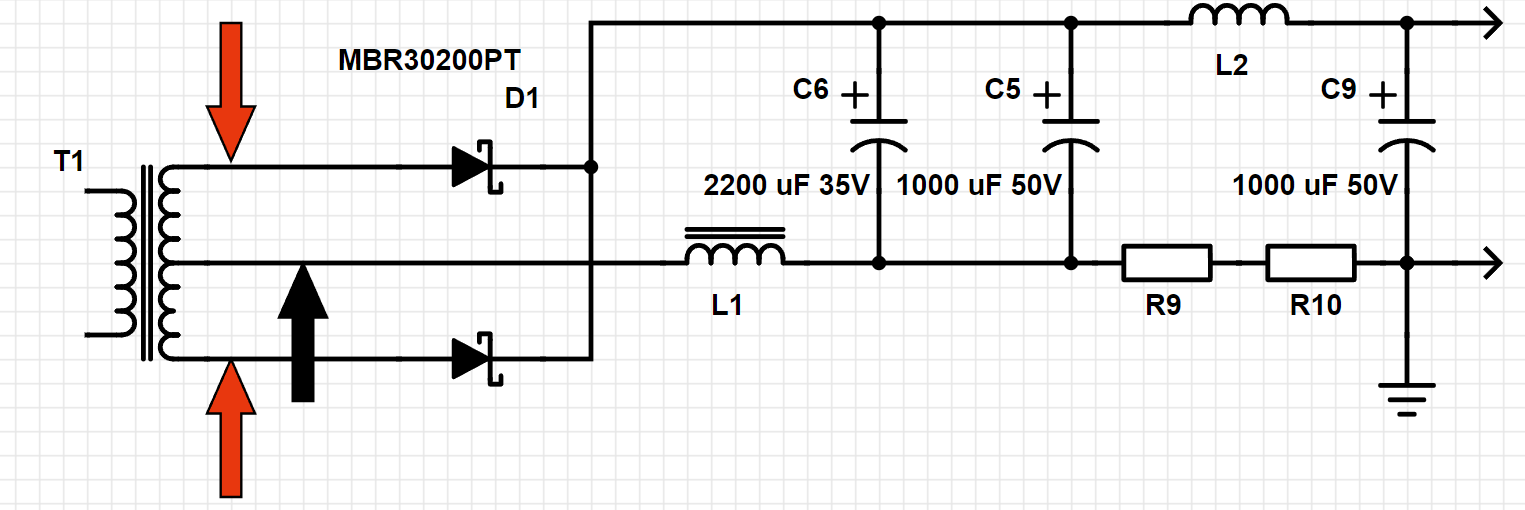
When transformer T1 is removed, it is OK to connect the power from separate power supply, positive to points marked with red arrows and negative to point, marked with black arrow. This imitates (except its DC instead of AC, but its OK) the transformer and puts voltage through the circuit to the output pins. On the way we have a choke L1, couple of low ESR caps for smoothing, small choke L2, couple of shunt resistors R9 and R10 (to measure current), final output capacitor C9 and thats it. So now I can confirm, that output circuit is OK. Next – lets try to test the input circuitry, also without transformer.
The primary part, judging from the drawn schematics, should be designed using Half-Bridge topology.
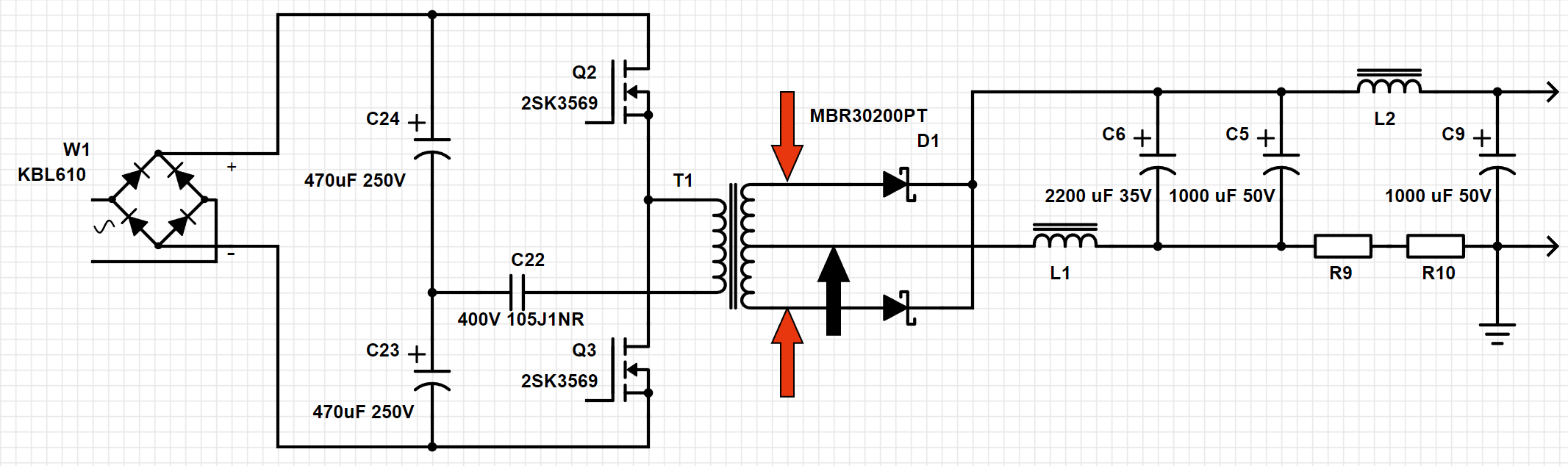
Half-Bridge topology is quite simple, two big capacitors forming capacitive divider, two transistors and one more addition, polypropylene capacitor C22. This capacitor is rarely found in cheap power supplies (AFAIK, might be wrong), its primary purpose to block DC currents to prevent transformer core saturation. There are some facts that we should take into consideration, before diving deeper, as those might be the cause of the problem:
- High side FET needs floating driver
- FETs handling full input voltage, but transformer has do deal only with half of input voltage.
- Should be no switching ringing
And this leads to our second suspect – is the high side FET really driven by floating driver ?
2024.04.04
Another spare minute, spent on further diagnostics. Regarding the floating driver – should be fine, transformer is present and its not the first part I would suspect in the SMPS. FETs are proper voltage, so it should be also OK. Ringing is a bit more complicated thing, need oscilloscope for checking, even if I have it, I wouldn’t suspect ringing in a first place, so lets keep it as a plan B. Or C. Or next to what ever letter we are at now  . Lets pick our next suspect – FETs in most cases are controlled by something, either directly by TL494 or using some sort of gate drivers. Lets update our schematics:
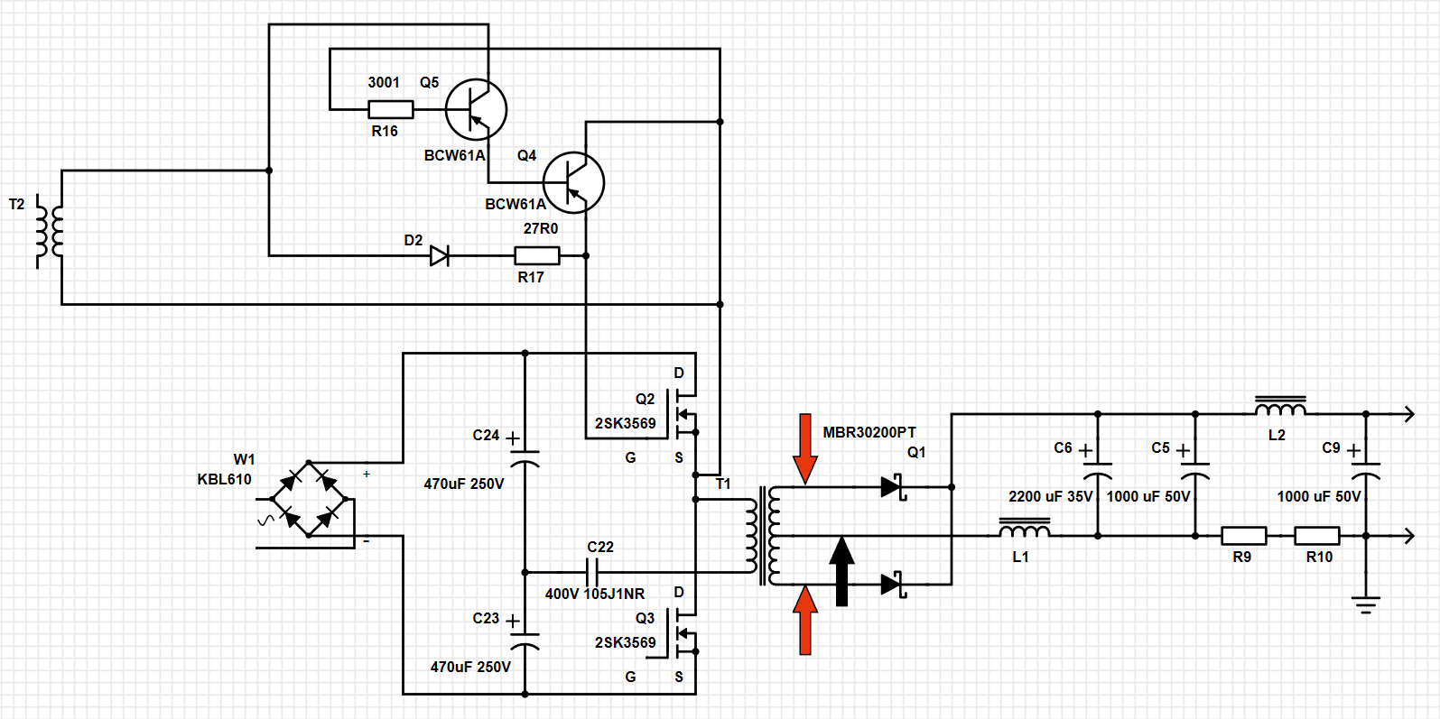
If I have not made mistakes finding traces on PCB and transistor part numbers on the Internet (transistor marking BA), we can see that there Q5 and Q4, along with couple of resistors and diode are controlling the Gate of Q2 and those BJTs are controller from transformer T2, which makes it floating. This part of PCB looks like this:
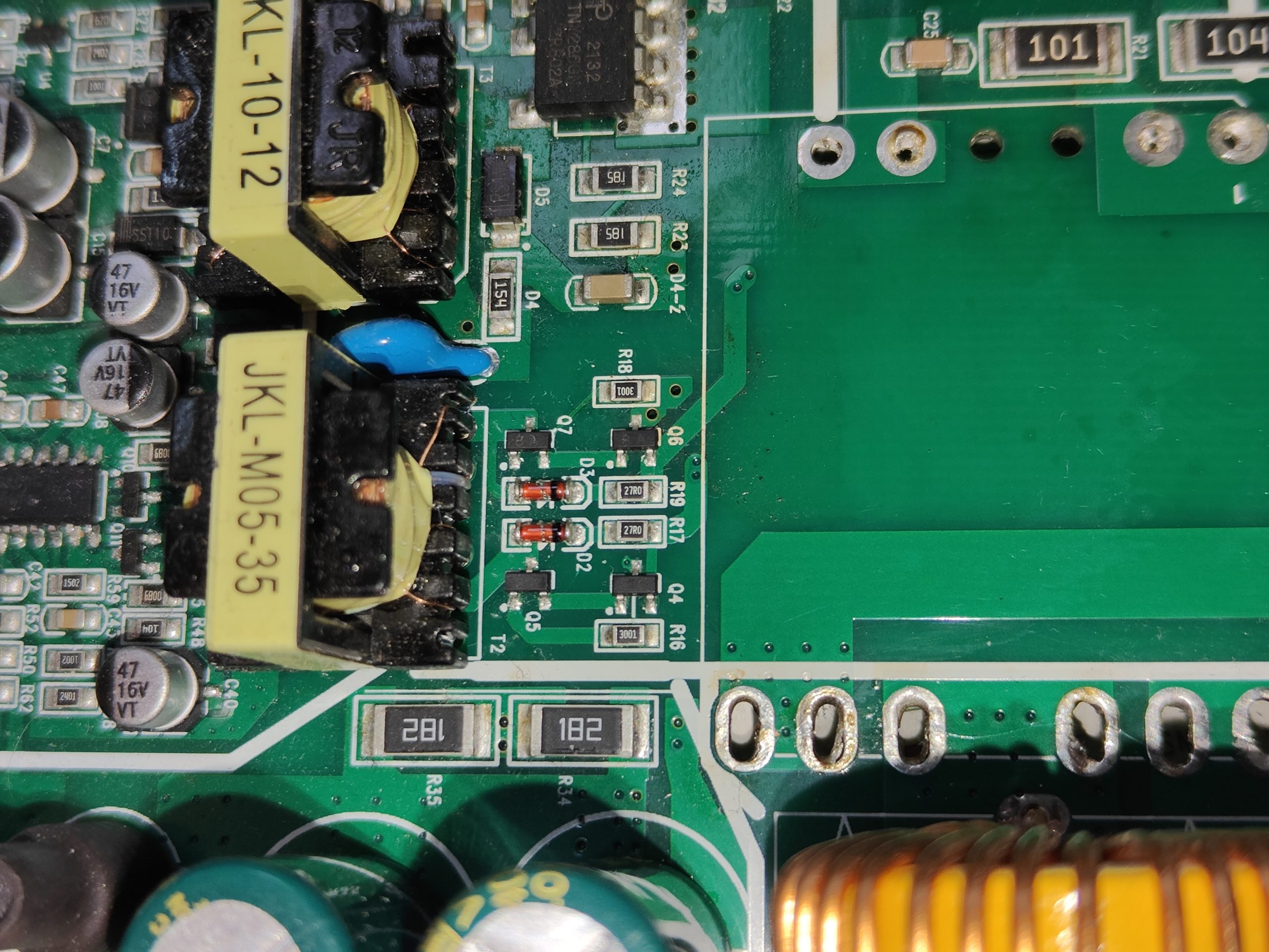
Ale as we are here, lets quickly check transistors Q4, Q5, Q6, Q7 and diodes D2 and D3. And here lies the fault – transistors Q4 and Q5 are shorted. That means they do not control the Q2 transistor, so it can be in some uncertain state, if its fully open, then its a short circuit every time when Q3 opens and everything blows. If its semi-open (is there such a word at all  ?) or closed then power supply could even somehow work, which I noticed during previous test after repair, on low current power supply was working, but when current raised – all popped again. Lets wait till new transistors arrive and replace them
  .
.
2024.07.12
Transistors arrived and replaced, I bet cant even tell the difference .

I picked the transistor with BA marking by EVVOSEMI, which is 2SA1015 transistor (datasheet). It might be incorrect, because manufacturers could mark some different transistor with same letters and the original letters are a bit different shape and spacing, but lets think that its because of new manufacturing batch and I did not made a mistake.
Damn, the transformer ferrite fell down and now its broken. Does that mean I will have to make a new transformer ? Or maybe somebody from my readers could send me the faulty board to take the transformer out for testing ?
For OktO:
My guess we should concentrate towards dead time of the TL494, probably it needs to be adjusted. Dead time ensures, that both transistors would never be open at the same time, creating direct path for current to flow from positive to negative, thus effectively shorting the power supply on the high voltage side. Pity cant check with oscilloscope, how the transistors are switched and if their working time overlap because Is still have no transformer  . Bet lets start from the current regulation, which you mentioned. Started to draw some schematics, it might still contain errors and surely is not complete, but it will give some insights whats going on.
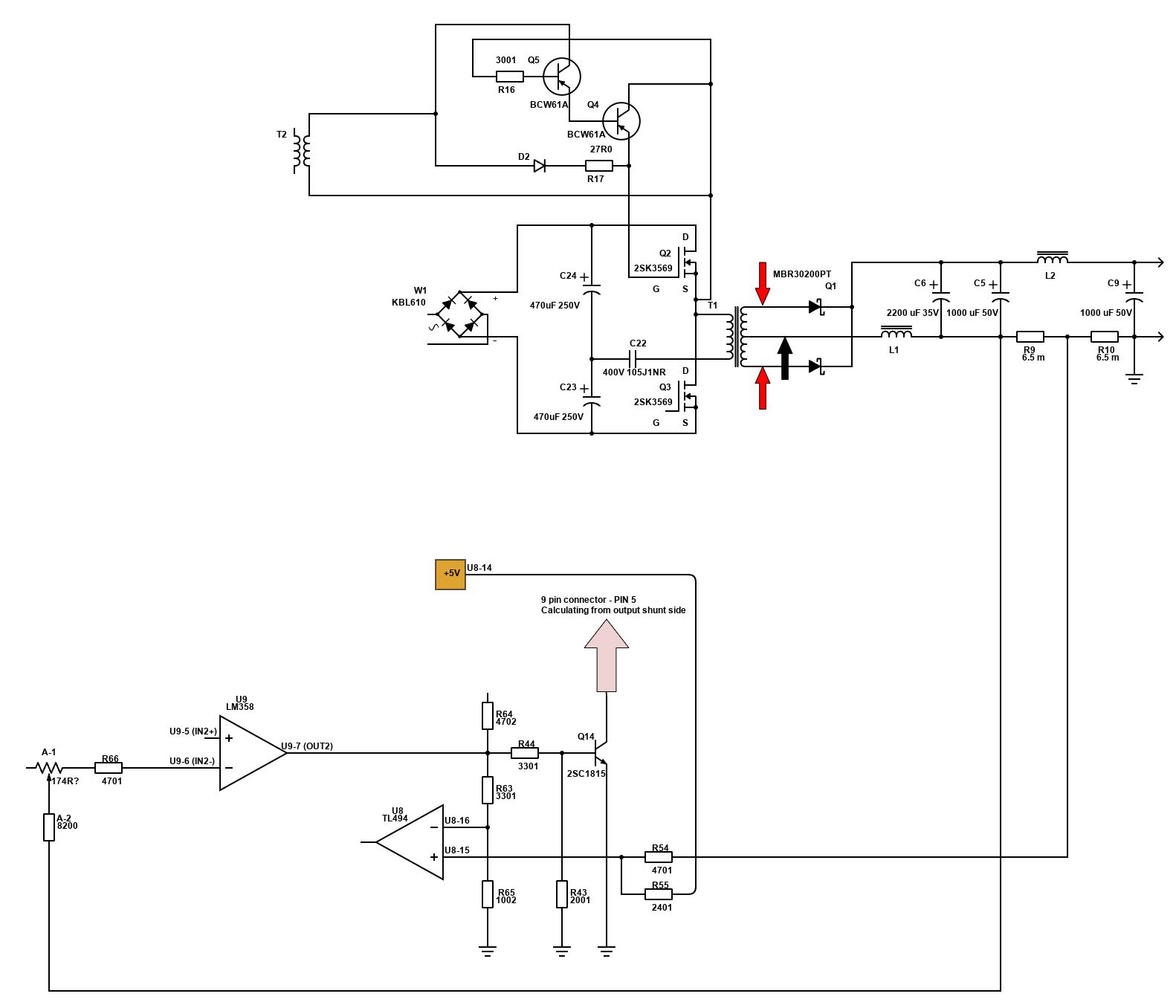
Feel free to correct me if you find a mistake :). U8 opamp is inside of the TL494. In theory, current limit is set by this opamp, pins 15 and 16. Normally, if voltage drop on shunt resistor R9/R10 is more than preset value, opamp starts adjusting output voltage. Was surprised, but it seems, that pin 15 is connected between two shunt resistors. I think that is because one shunt is used to overcurrent control and other shunt is used for indication on the current. Also we have second opamp in SOIC-8 housing LM358 for some reason.
Why I suspect dead time ? In my power supply, after I replaced both burned transistors and diode, it was working to some extent. I was slowly raising voltage to raise current and it popped again at about 6 Amps. So must be related to control, because power handling part was working. To kill both transistors you have to open them both, making a very nice and shiny short circuit on the high voltage side, which instantly damages transistors and eventually fuse. As the control was working, maybe the dead time is not enough for this transistor and while one is still closing, other is already open, whilst load is increasing and here we have magic smoke coming out.
Started to analyze the schematics from TL494 side, at the same time checking the power transistors control signals. First connection is made at TL494 pins 8 and 11. This confirms, that dead time exists for transistors Q9, Q10, Q11 and Q12 (but not the power transistors!).
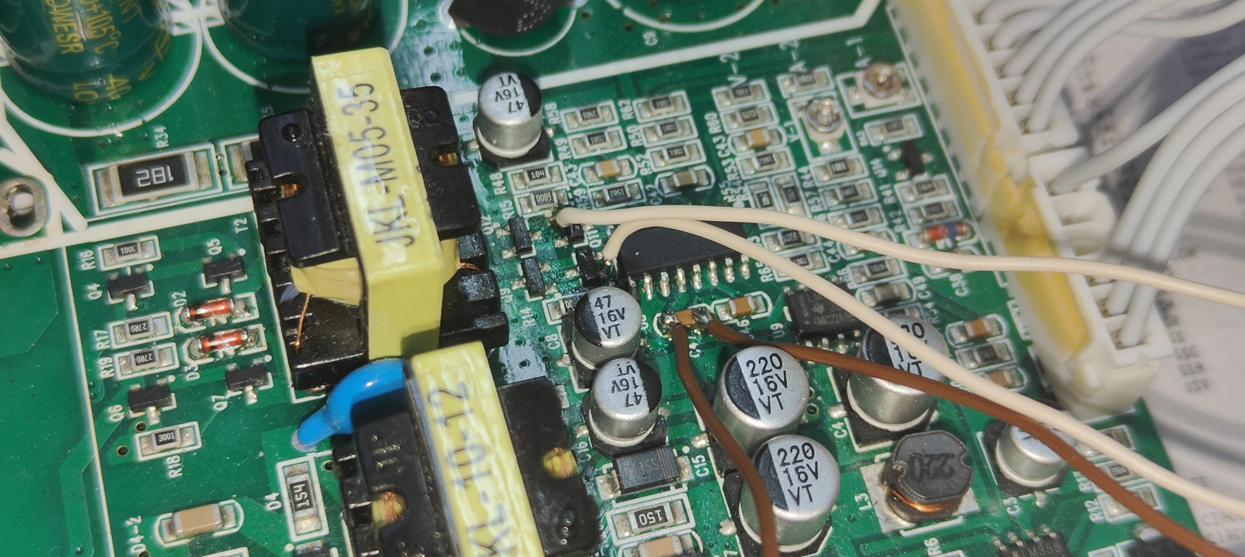
Brown wires – power supply (+12V and GND), white wires are control outputs. The signals on the oscilloscope are not so bad:
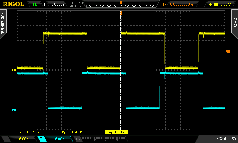
The switching on channels has some delay, not happening at the same time, but that delay is about 1,8 µs. But lets follow the controlling signal path and see whats happening there.
Removed the isolation transformer for better access:
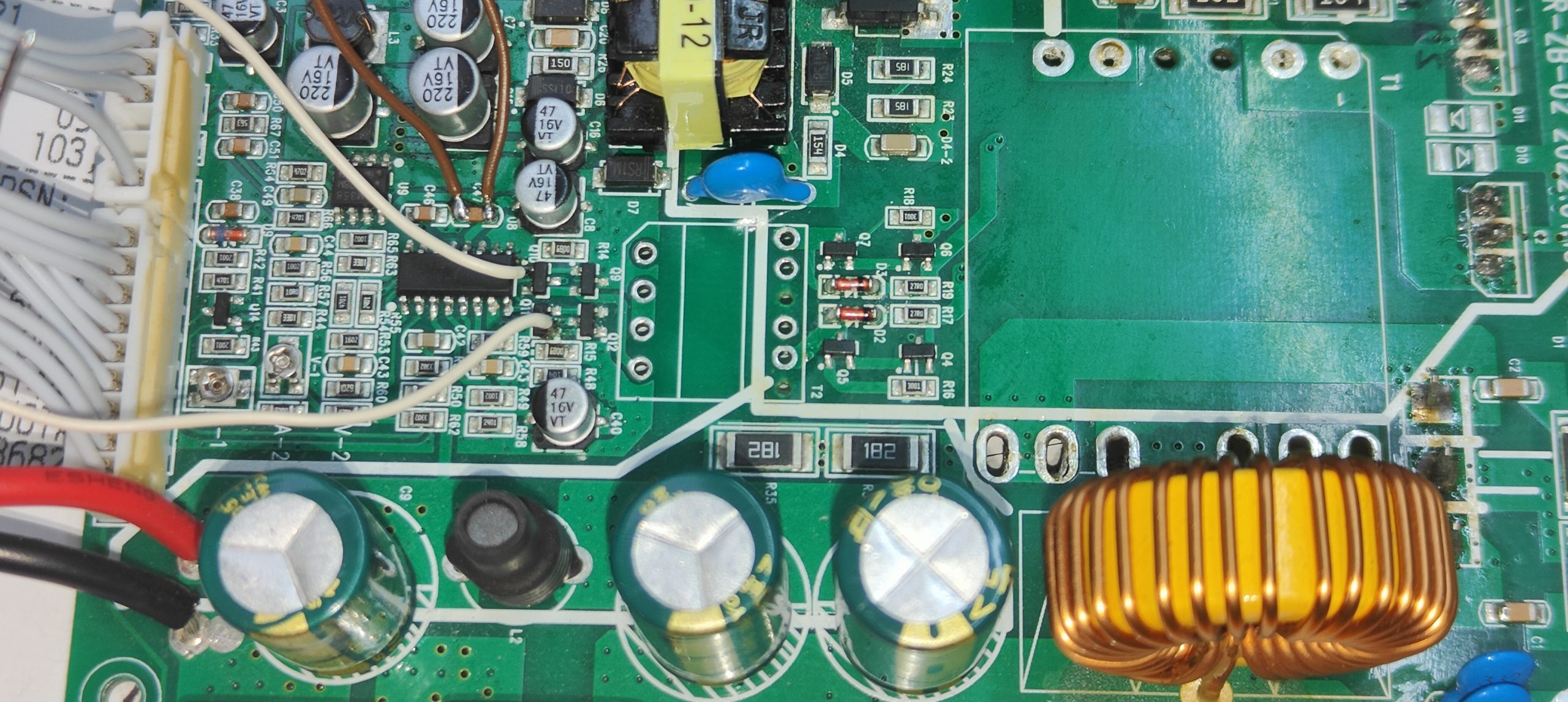
And updated the schematics:

Remark – transistors, marked BA are 2SC1015-H, marked HF are C1815. Four BA’s (Q4, Q5, Q6 and Q7) already replaced, because they were burned, before continuing I will also replace both HF’s and BA’s in push-pull transformer driver circuit. Just to be sure. Logic simple, chinese power supply, probably parts are taken from faulty manufacturing batches, so just to be sure, lets replace all, as OktO did. It seems, that C1815 is not available, but according to their really shitty and uninformative datasheet I managed to pick a substitute, which I hope will work in this schematics – Toshiba 2SC2712-GR.
Signal from TL494 is Ground, which is pulled up by R14 and R15 resistors to 12V. Signal at the transformer input:
To be continued…
Thanks for the comprehensive video photos. I had the same problem with the KPS605 df. I also replaced the transistors with ones purchased from aliexpress and the powerful diode. I also replaced the TNY277. Oh miracle, the power supply worked normally. I decided to turn on a brush motor at 12 volts and a current of 1, 5 am. And suddenly boom. Power stopped working. Fuses 3.15 am. it burst into pieces. This time the transistors and the TNY277 chip did not burn, nor the powerful diode. There is no short on the 220 volt input, but when I put a new fuse, boom again.
I’m looking forward to the continuation of your article. I’m wondering where I’m going wrong. Maybe it’s a problem with the controller?
Exactly the same fault.. The product looks good, but the same fault is upsetting. I’m looking forward to the continuation of the renovation story.
Bei mir fehlen die 2kondensatoren (blau) im Gerät KPS1505D.
Bitte um die Bezeichnung darauf.im voraus . Dankeschön.
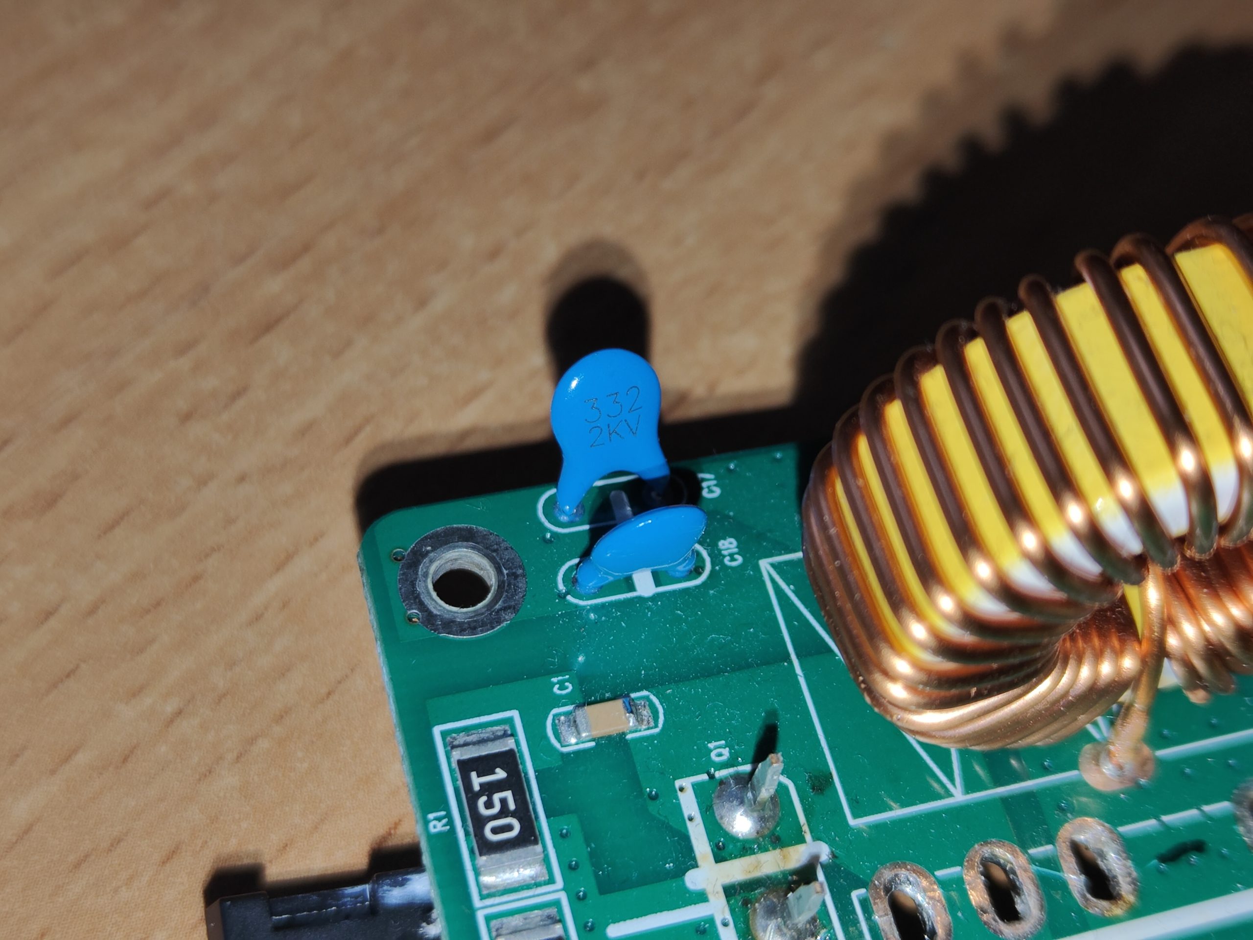
Hello Manfred, if Google translate correctly translated, you need values of two blue capacitors. Its 332 2KV (3300 pF or 3.3 nF and 2KV).
Hi, great work!
It would be nice to see the continuation, you have done very valuable work and research so far. Would like to know if this is comparable to the Hanmatek HM305 and HM310. They look like a similar half bridge TL 494 topology. Especially, the pinout of the connection between the Power board and the Control panel board would be awesome to have!!
I have two sources and I have tried to replace what I barely know and have reviewed and it is wrong.
First I changed the mbr30200 and then the two k15a60d, mine uses where the thermal paste goes, these 3 components were shorted. I changed them and connected them and the fuse blew on one and didn’t read anything. I’m going to check the transistors that you had burned out, let’s see now
I have an Eventek KPS1505DF 30V/10A switching power supply that works the right way „sometimes.”
Do you think it’s repairable?
I can’t find a Service Manual for it anywhere.
Any help you could give me would be greatly appreciated.
Hello Nathan,
Everything is repairable, but that is rather philosophical question than engineering/electronics. In your case, if the device sometimes ir working and sometimes not – first I would suspect bad contacts in welding/wiring/connectors/etc. Unless it stops working under bigger load, then maybe its heating issue, thermal camera would show… Not too much to advice with such a short malfunction description, but on the other hand it would still be guessing.
For commercial products almost in all cases there are no service manuals available for public. Back in USSR every device had user manual with included schematics, PCB view, parts list and working description, with oscilloscope images if applicable, those days are long gone 😀
Thank you for the post. Well written and I came here because I was looking also for some ideas on how to continue with my faulty power supply (KPS120DF) as I end up exactly the same issue: After replacing the 2SK3569 the power supply worked, but not short safe -> everything blows again. After replacing the BA’s and 1 HL transistors I have the problem, that the output and display show only 0.0V / A.
(there was a Q9 with HL marking (NPN) shorted with approx 200 Ohms.
I suspect that I have an issue with the TL494C so I have ordered them. The ref 5V is there but to go sure I will replace it as well. Will keep you posted, should arrive soon.
So your post is still read, please keep it up. Hope you will find soon a new transformer-
OktO
Posts like that are the best motivation to continue 🙂 thank you!
just a quick update:
I did look little more around and found out, that on C1 and C2 I do have around 40kHz. So this would mean the TL494C is working. At least it is generating the PWM. Replaced everything again (still waiting for the BA’s and HF’s, but used for testing Y1’s and Y2’s. I need to mention, that 1 of the cables to the Voltage selector was torn off due to constant installation and removal. So I solder it back.
Slowly increased the Voltage from 0 to 110V, nothing blew up. So I tried to turn up to 230V and still good. Set to 5V and now I am ready to test. We need to find out now, which area is responsbile to stop the pwm / output as soon the current increase above the threshold value and not blow up every again. So any feedback would be good. @
Dainius: sorry to missuse your blog as forum 🙂
No worries, I’m glad to have some chatter here 🙂 Now I am thinking to wind the transformer myself, for testing purposes it will do :).
oh man, you want believe what I found out.
But first let me correct the my typos above:
post 1: HL -> should be HF marked NPN transistor
post 2: I increased the voltage on my adjustable isolation transformer from 0-230V (while similar but weak mosfets were in), then set the power supply to 5V.
then, I thought let’s do some test below 1A to not blow up the MOSFETs, all was good. So I solder back the Aliexpress MOSFET, to make test with them, and BOOOOM. Everything blew up again. This are fake MOSFETs. unbelivable. So I search youtube and the net and it is full with fake MOSFETs from Ali, so if you have the same, please check first if your moset is able to drive the amount of 2-5 A
how can we attach pictures here?
Dude, buying parts at AliExpress is major fail, never do that again :D. As for the pictures – I’ll fix it in couple of days. Probably on Monday.
Thanks Dainiaus updating your post 🙂
Meanwhile, my power supply is fixed and working. All of the BA’s and HF’s were leaky. When meassuring, it looks ok (like 500 Ohm from b to c and c to e) but under the thermal cam you can see exactly the issue. They got very hot. After replacing them, nothing got hot any longer. See attached Photo. So clear recommendation: Replace all 6 BA’s and all 4 HF’s (for my board at least). (ps: and check if bought mosfets are fake ones, like mine it was showing as resistor only, all 10 of them)
of course, I meant b to c and b to e 🙂 so like we also test a transistor in diode mode…
Looking at the board in infrared spectrum is a good idea 😉 I will surely give it a try when testing my board! Well, good luck with the power supply and lots of solved electronics engineering challenges to you !
Hi Dainius
I can’t post nothing, is the blog closed?
Bye
Hi Dainius,
Ok, Now I can post….
Sorry if this blog is becoming a forum but I discovered this a couple of days ago looking for something that could help me repair my
Eventek KPS3010D power supply (30V 10A) and I saw that you are a very knowledgeable electronic engineer investigating your power supply.
I’m following you to see how you can fix it.
Mine has always been OK, but suddenly with a load of 5V 2mA after a few seconds it turned off completely, display, green LED and of course the voltage on the load.
If I leave it off for a few minutes, then it restarts but after a few seconds it blocks again.
In the few seconds that it remains on, the output voltage regulation and the current limitation work regularly
even with loads of 12V 2 A (I have not tried beyond that).
Also, this happens even no load is connected.
I have verified that the motherboard is practically identical to yours on this blog, even the numbering of the parts is identical.
Since you know it well, can you give me some indication of the probable cause or some measures I can take?
Thanks
Carlo
More infos:
I can confirm that no parts became hot, no smoke.
Furthermore I’ve read the datashhet of TNY277 (auxiliary supply for front panel), so, they said that if in case of overvoltage (that I do not notice) this chip goes in block state until the main power plug in disconnected. Well this is my situation.
May be TNY277 faulty?
Bye
Carlo
Hi Carlo,
Everything is possible, to be sure about TNY277 lets check if the power disappears, for that you could take your oscilloscope, if you don’t have one – cheap oscilloscopes from AliExpress would do fine for this purpose, plus they will be battery operated, thus galvanic isolation (it might be important when repairing power supplies). Otherwise always use galvanic isolation transformer for the repaired power supply and only then measure with oscilloscope. What you need to check first – power supplies for TL494. Main power supply comes from auxiliary/standby power circuit, driven by TNY277, check voltage on TL494 pins 12 (power +) and 7 (GND), its the power supply of the TL494 and rest of the circuit. Check also for the waveform after the failure occurs, maybe its plain zero volts, or maybe it has some strange pattern. Most probably not related to the fault, but internally, TL494 has stabilized 5V power supply and it uses those stable 5V to power various control circuits inside and outside of TL494, so if main 12V power is OK, when power supply shuts down, then check for those 5V at TL494 pins 14 (+5V) and same 7 (GND). There could be something else to continue, but lets get you started with those two things. By the way, is the failure repeatable ? I mean, if its bad contact somewhere, it could fail randomly, but if you have a failure always repeats at 5V 2mA then its more interesting, but I have some ideas :).
Hi Dainius,
Thanks for your reply, I will do ASAP and I will report the results.
Anyway, this fail is repeatable, and also with other loads (12V 2A) or with no-load.
Bye
Carlo
Hi Carlo,
No worries, take your time :).
Best regards
Dainius
Hi Dainius,
Some news, I measured the voltages between pin 7 (GND) and pin 12 (+12V) and Pin 7 (GND) and pin 14 (+5V) and when the
PSU is working normally the voltages are correct and flat.
Instead when after a few seconds it goes into failure (even without any load connected), both voltages go to flat zero. I don’t see any strange waveforms.
I used my battery pocket O’Scope DS203.
NOTE:
A couple of weeks ago (before finding this blog of yours) I asked on a forum and the other day a user replied that from my attached photos
according to him he sees that the two 470uF 250V filter capacitors seems losing electrolyte and often is the cause of the issue.
Looking deeply on my board I see that one of the two actually seems to be leaking.
I will remove them and check better.
What do you think?
PS: Is your PSU repaired?
Bye
Carlo
Hi Dainius,
I removed the two 470uF 250V capacitors and underneath, on the PCB, I can see some electrolyte dry residues. Also, the solder joints of the nearby 1uF 400V capacitor (C22) are green (they are oxidized) so I removed it and cleaned the PCB in that entire area.
I measured the capacitance of the two 470uF capacitors with the DMM and one measures 417uF, the other 440 uF.
Ciao
Carlo
Hi Carlo,
Good job, you proved, that standby power supply has a fault and that limits us to a small portion of the schematics – easier to find a fault.
I don’t believe, that the fault would be caused by those capacitors. I mean, yes, if they are leaking, go ahead, just replace them, but they are not the part of standby power supply schematics. Look at the last picture in the post, they are marked in that schematics as C23 and C24. They are used as bootstrap/voltage divider capacitors for the main power supply and even without them the standby power supply should work. On the Internet I encountered some intentional misguided advises, so you have to think or double check :D. Ok, have to mention, that if those capacitors are dead and shortcircuits the high voltage line, then also the standby power circuit wouldn’t work. To understand look at the last schematics again. Find a diode bridge W1. Its missing the left part of the schematics, because, basically, there is a bunch of irrelevant filtering parts, fuse and 230VAC connector. So, 230VAC comes, after the diode bridge it becomes about 325VDC, with positive polarity on C24 plus pin and negative polarity on C23 negative pin, so both capacitors are charged to 1/2 of the DC voltage. Now imagine, those capacitors would be shorted, effectively shorting the bridge and the main 230VAC fuse, well, yes, fuse pops, nothing works and that is the only way how this part of schematics can make standby circuit not working. Naturally, fuse cant heal, so fault is permanent. Experiment for you, to prove, that those big capacitors are not the cause – measure the DC voltage on the W1 bridge + and – pins, or on C23-C24 capacitors, on the pins which has bridge connected. There will be 325-350 VDC so use multimeter, because your oscilloscope will be fried if its probe has no measuring divider. When the fault occurs, I bet you will still have those 325VDC.
Before that W1 bridge, there is another, small diode bridge, with its own DC filtering capacitor (10 uF 400 V) – this is the power path to TNY chip. You, probably, found it as C22. But easy way to prove to yourself that this high voltage cap has nothing to do with malfunction – measure voltage on its pins (carefully, 325 VDC) using multimeter, your oscillo might be fried if probe has no voltage divider. If there is always 325-350VDC – that means TNY has power supply, but the output from the TNY is disappearing. That almost certainly will mean, that TNY is faulty. Not 100%, because it has some other components outside the chip that could fail, but very likely, so if input voltage is OK, just get a proper TNY chip. No, not from AliExpress, use reliable suppliers. Digikey at the moment has ~60000 pcs, price 1,63€ – Digikey web with TNY. Get one, its cheap, easy to replace and then test how it works. If the same, then we will search for the fault in feedback and control components, which are outside the TNY chip.
Best regards
Dainius
P.s. Are you sure its electrolyte under the capacitors ? Not the solder flux ? Sure ?
P.p.s If you have oscilloscope with divider, set to x10, that will divide voltage by 10, so it will show 32,5VDC. Probe with divider looks like this. If your oscillo can handle at least 40VDC (most of them do) then you can use oscillo for the measurements, at the same time you will learn how voltage graph looks like, maybe its flat, maybe has some form :).
P.p.p.s Nope, mine power supply not finished, as it has broken main transformer, I still have to wind another, no time for that. Got second similar power supply, not sure what fault it has, but will try to repair anyway 🙂 Then maybe will wind a new trafo. Why I don’t hurry – because its not my lab power supply, they are not good as lab power supply. For standard use I have BK Precision 9104, for some high power needs Mastech HY3020 (linear). BK precision covers 99% of requirements, especially with microcontrollers and other logic.
Thanks for the very exaustive e complete answer.
For now I have ordered 2 new 470uF 250V capacitors and in a week I will mount them and verify what you suggested.
Note:
In my PSU there is no the small rectifier bridge dedicated to the power supply of the TNY277, the supply is surely derived in parallel after the main (only one) power bridge.
Second note:
About the loss of electrolyte, yes I am sure it is, the fact that the solder pads of the capacitor C22 1uF 400V which is very close, are covered with green oxide, is a sign that the capacitors C23/24 are leaking and corrosion has started.
Bye
Ok ,strange to have those caps leaking, probably they were really bad quality. Drop a link of those 470uF caps, to see what you picked :). I’d recommend something like this capacitor, but that’s my technoelectronicsgeekish opinion :D. also add some photos of your PCB, hard to comment what I haven even saw it :). Replace also that C22. Oh, yes, almost forgot – order the TNY chip and replace at the same time. Its cheap, most probably it TNY fault, so there are pretty good odds, that repair will be a lot faster, compared to replacing the caps now, then waiting for another week for TNY. Time is money 😀
On the site you linked, the capacitors with a diameter of 18mm and a pitch of the radial pins of 8mm are not availables, furthermore the shipping cost is about 20 dollars (I’m just an hobbyist 🙂 ) as on other similar sites.
I opted for a local Italian supplier who sent them to me for a few Euros, I hope they are adequate.
I found the TNY277GN chip for 3 Euros from a TV repair workshop near me (I live very close to Milan), here too,
let’s hope it is original chip as he is a professional repairman.
I will start by changing the capacitors, then if not solve, I will replace the TNY.
I have a Hot Air desoldering station, do you recommend removing some components around it to make it easier to replace the TNY?
Thanks, Bye
On the site you linked, the capacitors with a diameter of 18mm and a pitch of the radial pins of 8mm are not availables, furthermore the shipping cost is about 20 dollars (I’m just an hobbyist 🙂 ) as on other similar sites.
I opted for a local Italian supplier who sent them to me for a few Euros, I hope they are adequate.
I found the TNY277GN chip for 3 Euros from a TV repair workshop near me (I live very close to Milan), here too,
let’s hope it is original chip as he is a professional repairman.
I will start by changing the capacitors, then if not solve, I will replace the TNY.
I have a Hot Air desoldering station, do you recommend removing some components around it to make it easier to replace the TNY?
Thanks, Bye
Yes, those capacitors are just an example of good quality caps, but shipping is rather expensive. Probably you selected to purchase directly from Digikey? I use local electronics store for ordering, they gather a bunch of orders, and when they order a lot of parts from Digi and then shipping is divided between all of them, so eventually its just several cents. You can use any local supplier, who can order from Digikey, Mouser, Elfa, Farnell, TME. TME is actually in Poland, so shipping is not that expensive, when ordering a bigger quantity. What I meant – only good and trustworthy suppliers should be used for electronics parts. Ok, lets do your way, first replace the caps :). With TNY desoldering its going to be a challenge – it has big copper planed around to effectively dissipate heat from TNY, when it is working and heating by itself, so those planes will dissipate also the heat from desoldering. To make it easier – put a blog of solder on the side with 4 pins, they are all connected together on the same cooper area, keep it hot with with your regular solder and use hot air gun for other side, which has 3 pins. After removal, clean the left solder from the solder pads. Putting the new one would be easier if you put a small solder amount on the pin 4 pad on PCB, because that place has easiest access. Then solder the TNY to the pad. After that check if TNY is aligned properly and solder all the pins left :).
Hi Dainius,
I have not disappeared, but the supplier of the two 470uF 250V capacitors sent me the 2 capacitors but they are from different manufacturers and of different sizes.
The nominal capacities are the same, but I measured them and the actual ones are quite different. I know that in this configuration they should be identical.
I have reordered them, I will receive them this week.
Hi Carlo,
You have some supernatural abilities – I’ve just thought about how are you doing and voila, new comment :D. Don’t be too strict with the capacitors, the main thing is to have both same capacitors and fit them into the PCB holes and the power supply box. The voltage rating can be higher, more important for it not to be lower than 250V. In proper caps are not available (hard to believe, but it happens), you might even hot glue them to the transformer and use wires or thicker copper strand from monolithic electrical cable (the same as used in house electrical installation) to connect them to proper PCB holes (just don’t mix the polarity, otherwise you’ll have some fireworks).
Yes I know these possibilities.
A question, if the capacitance of the two capacitors is different does it affect the output ripple due to the different voltage in the two adjacent half-periods?
If you would be designing the power supply, then you need to make sure the capacitance is equal for both capacitors, otherwise it would cause overvoltage on one of the capacitors, increased and most probably asymmetric ripple during cycle transient. But if you put two same capacitance capacitors, I think the major influence on the ripple would only be caused by lack of capacitance (the more capacitance is lacking the bigger the ripple) and how much the current the load consumes (more load = more ripple, whilst with no load, there might be no ripple at all). You would have to calculate all this to be on the safe side, but as the power supply is already designed, luckily we don’t have to :D. I wrote about similar case, with oscilloscope images without load and with load I already wrote here.. The power supply is a lot smaller, but the principles are the same.
Hi Dainius, good news!
Today I replaced the two 470uF 250V capacitors and, as you predicted, the fault was not resolved.
Then I replaced the TNY277G, struggling a bit due to the limited space, but in the end it solved the problem.
It has been working for a couple of hours with a load of 12V 1.8A and it no longer blocks as it used to after a few minutes or seconds of operation.
In any case, after further tests I will confirm whether the repair is definitive.
Thank you very much for your support,
Carlo
Heeey Carlo,
That’s a good news, glad you managed to repair the power supply 🙂 Electronics is easy when you have someone to talk to :). For me it happened that during the talking I came up to the solution myself, so sometimes you don’t even need to talk to some electronics guy, just build a logical path of thoughts during the conversation with anyone 😀 yourself, for example 🙂 well, OK, some experience and knowledge is required, but for that you have this blog :D. And that made me think, this year I would probably like to visit Italy 🙂 its not going to be a first time, but its been a while already 🙂 would be a nice weekend trip 🙂
Hi Dainius,
Which city would you like to visit in Italy?
I recommend Rome, for me it is one of the most beautiful cities I have seen, the fact is that this year there is the Jubilee so there will be many more tourists than usual and therefore a lot of crowds around.
I live near Milan, it is not exactly a city of art, but it has its beauties.
If you come let me know.
Power supply:
Another 5 hours under load and no problem, the voltage and current potentiometers works regularly.
I also ran it for a few hours without load (even when idle it would break) but now everything is ok.
At this point I consider it repaired and working.
It’s true, sometimes you just need to talk to someone and magically you get some insights even before the answers, you certainly need to have some basics (in this case electronics) to solve the problem.
Thanks again
Carlo
Actually I was in Rome last year, so now it could be other city 🙂 Could, probably, be Milan, my aunt lives there nearby in Bergamo :D, might be a good opportunity to visit. With the power supply, I guess, the repair can be confirmed as done :). Now I am working on similar cheap power supply, Hyelec HY3005BC, so it should also have a post in blog after the finish 🙂
@Dainius did you finish creating the schematic? I picked up one like this the other day, my problem seems to be that the output voltage is stuck at +-12.5 volts. The weird looking potentiometer does nothing when you rotate it. A schematic would have been nice to follow.
Hi Binto,
All I done is in the pictures, so at this point cant say I have anything more. But I believe it would be great if you could continue and add your part of the schematics, this way, with mutual effort we could move on. I used Digikey tool Scheme-it for this drawing, if you would also register there, I could share the schematics and you could continue in the same tool and then share the results.
Hi Dainius, I looked through your schematic diagrams together with the chip reference pdf to understand a bit more about all this. Looks like you have already captures the „engine” behind the main power generation. Basically the TL984 control how hard it drives the T1 transformer by PWM, which is how I believe it create the variable voltage. I didnt want to breakout my old oscilloscope, so I tried measuring the output channels on TL984 using my multimeter set in AC mode. One of the channels output a fairly large voltage where as the other looks dead. I ordered a couple of replacement TL984’s on Ebay yesterday. Waiting for chips to arrive. Thanks a lot for creating this, you never know who it helps out.
Yep, most of the voltage creation process is already in the schematic and you’re very welcome to use it :). Though eBay might have counterfeit chips, so using them is trying your luck and in the end, if the power supply will not start working, you wouldn’t be sure if its new chip or something else on the board. I said multiple times, use only reliable suppliers and genuine chips… Heh, never used multimeter in AC mode to measure outputs or waveforms. Though if your multimeter has true RMS calculation capabilities, it might just work 😉
I have one of the many low cost Chinese bench power supply. It’s a Vlifree DCP10A which is a 0-30 Volt 0-10 Amp. I put a direct short on the output. Despite having the current limit set, it blew. I was hopeful of getting it repaired since the display, voltage and current set were operational. It just would not output voltage.
The design of this supply is similar to the one described, but with some notable differences. The line side looks very similar with some of the caps appearing identical to the OPs. One change is the voltage regulation circuitry (TL494 and associated transistors) is on a smaller daughter board mounted perpendicular to the main board.
I focused on the output stage which was the most likely area for a problem. The output stage was simply two schottky diodes off of a center tapped transformer secondary. There was also an inductor and several capacitors for filtering. Additionally it had an N-chanel MOSFET whose function was to act as a gate between the internal voltage and the positive output terminal of the power supply. The power supply has a button labeled “Output” which, when pushed, connects the internal output to the output terminal of the supply through the MOSFET. Since I could measure that there was voltage being produced inside the supply, the likely problem was the MOSFET. Indeed, that was the problem. I replaced the MOSFET (a P75NF75, reference Q5 on my board) and the supply began working.
A couple of notes on this model. It’s 120 VAC only. There’s a cutout on the chassis to hold a 120/240 VAC input voltage selector, but it was hidden by a label and the switch was not equipped. The label indicates there is a TL8L250V 5*20mm fuse, but there does not seem to be a fuse in the unit. The output Schottky diodes and the MOSFET are mounted directly to a single heatsink without insulators which means the heatsink is at the output voltage.
A final safety note. The line side caps in series are charged to over 300 Volts and the voltage slowly bleeds off when the unit is unplugged, so take appropriate precautions before sticking your hand inside the unit.
Hi Dainius, Giday from Australia to Lithuania
I haven’t received my Wanptek 3010H yet but when I do I want to replace some of the caps on the output side.
I’ve ordered them but it occurred to me reading though this long post that I never saw the part where you actually repaired that power supply. I checked again, scratching my head.
I was thinking to add to your post and making it an even more effective source of knowledge to help fix other similarly affected power supplies, I could insert voltages at several places on the schematic so that others who are trying to repair their unit could reference what they should find at particular components on a fully working unit. But then I realised that if that was beneficial, you would have done that during your repair cycle. You must have done a lot of measuring and not taking notes because it was a faulty unit with suspect voltages. Maybe not such a good idea after all.
Thank you for your post all the same. Mine isn’t here as I said but I have copy & pasted the main body of this work for possible future reference in case yours disappears; it does happen.
Cheers mate,
Phil
Hi Phil,
First of all – why do you want to replace the caps ?
And you’re right about incomplete repair. The PCB board should be OK, but during the repair I desoldered the main transformer and it got into an accident – it fell to the floor and transformer ferrite core cracked to pieces. Didn’t rewinded the transformer on new core yet, thus no final check and verdict.
P. s. Nice to know people are reading my blog in Australia 🙂